12b4a SET - any critiques on this project ?
Last week, I actually built something cheap that works and sounds good from day 1 .
Any cheap mods on improving the performance ? All I have on my to-do list are CCS the driver and film-bypass the cathode and power supply electrolytics. I haven't bothered decoupling the power and driver stage (though each channel has a seperate CLC filter section).
Description at http://zobsky.blogspot.com/2008/06/12b4a-amplifier.html

Thanks
Re: 12b4a SET - any critiques on this project ?
Hello,
I would recommend to replace the LED by a resistor and bypass cap like you did it in the second stage.
The LED is a non linear element and creates some kind of "LED sound".
Kind regards,
Darius
zobsky said:
Hello,
I would recommend to replace the LED by a resistor and bypass cap like you did it in the second stage.
The LED is a non linear element and creates some kind of "LED sound".
Kind regards,
Darius
"The LED is a non linear element and creates some kind of "LED sound"."
My experience is quite the opposite. I have found LED's tend to introduce a very clean detailed and punchy sound. Resistors are much softer and more blurred. Capacitor bypassed will sound like the capacitor which most people say is no good thing (though I find the problem overstated).
SY has done extensive measurements on LED biasing and finds it a very low distortion option.
Shoog
Shoog said:"The LED is a non linear element and creates some kind of "LED sound". ...
My experience is quite the opposite. I have found LED's tend to introduce a very clean detailed and punchy sound. ...
Shoog
Thanks for describing LED sound.

Shoog said:Resistors are much softer and more blurred.
Shoog
Resistors are making current feedback there.
This current feedback can be eliminated by a high
"well known factor".
Shoog said:"The LED is a non linear element and creates some kind of "LED sound". ...
Capacitor bypassed will sound like the capacitor which most people say is no good thing (though I find the problem overstated). ...
Hello Shoog,
Shoog
The signal voltage drop at the ESR of the cap is much lower
than that dropping at the differential resistance of the LED.
This drop is what causes the influence in sound.
Shoog said:"The LED is a non linear element and creates some kind of "LED sound". ...
SY has done extensive measurements on LED biasing and finds it a very low distortion option.
Shoog
I remember SY recommended to add some additional current
to reduce the differential resistance and it's influence in sound.
What about bypassing the LED with a cap?
Kind regards,
Darius
You need an enormous capacitor to bypass an LED.
LEDs are great for biasing valves, but this might not be the ideal option. Like any diode, their slope resistance is nonlinear so they have the potential for adding distortion. The important thing is to maximise the ratio of the slope resistance to the anode load resistance so as to minimise the feedback voltage developed across this nonlinear resistance. 22k is a bit low. If the stage was the input stage of an RIAA stage, you could get away with it because the signal levels are lower and the distortion proportionately lower. On the other hand, although an LED might increase distortion in this application, it won't cause blocking in the way that a resistor capacitor combination might. I'd say, "Try both." After all, it's an easy thing to change, and you can decide which you like best.
LEDs are great for biasing valves, but this might not be the ideal option. Like any diode, their slope resistance is nonlinear so they have the potential for adding distortion. The important thing is to maximise the ratio of the slope resistance to the anode load resistance so as to minimise the feedback voltage developed across this nonlinear resistance. 22k is a bit low. If the stage was the input stage of an RIAA stage, you could get away with it because the signal levels are lower and the distortion proportionately lower. On the other hand, although an LED might increase distortion in this application, it won't cause blocking in the way that a resistor capacitor combination might. I'd say, "Try both." After all, it's an easy thing to change, and you can decide which you like best.
What about bypassing the LED with a cap?
A bypass cap of about 47uf seems to reduce distortion a little. In order to fully bypass an LED would require a huge cap which is not desirable or practical.
I remember SY recommended to add some additional current
to reduce the differential resistance and it's influence in sound.
I wouldn't run an LED at less than about 6mA. In my preamp I used a little circuit off the heater winding to supply that supplementary current. It tightened up the sound. A simpler result can be achieved with a resistor from the +B to the top of the LED.
Shoog
I think some of the troubles we heard at highest gain could
have been the transformer saturating, rather than anything
clipping the power rail as we had originally speculated.
Might try parafeed experiment with a larger external choke?
Just to see if DC saturation of the SE transformer might have
been the limiting factor.
It sure sounded great up to a watt or two! Certainly we were
not using the most efficient loudspeakers available to us.
Need to bring both Karlsons to one venue at the same time
for another audition.
Re: Se- 12b4
I got this schematic from diyasylum.com and I really don't know who designed it.
But if you have a very efficient (high sensitivity speakers), this will work (am using a 93db pair and it works).
Ciu said:Hello Alexq !
Would you share your schematics ?
I have some 6n1p and 12b4 on shelves...
Thanks !
R.C.
I got this schematic from diyasylum.com and I really don't know who designed it.
But if you have a very efficient (high sensitivity speakers), this will work (am using a 93db pair and it works).
Attachments
oldeurope said:Resistors are making current feedback there.
This current feedback can be eliminated by a high
"well known factor"
What Darius is referring to here, is the ratio: Ranode/[(u*Rcathode) +Rplate]. You are looking for something around 4 or greater, so that degeneration by the cathode resistor is small. It's an interesting concept, but my first guess is that you can't get there with this amp, at least not with this input tube. Estimating a cathode resistor of 500R that would give a factor of: 22k/[(60*500)+12000) = 0.52.
Sheldon
zobsky, I notice that the cathode resistor for the driver is fed from the anode of the output tube (assuming that the diagram is drawn correctly)
This will provide local feedback for the output stage.
It will however also present a difficult load for the driver tube,
Effektive load = 22k / (1+mu) = approx 3K. The resulting loadline is shown in the attached graph.
As can be seen the driver output will be limited to around 30V p-p. I think thios will only be sufficient to drive the output tube to max 1W, and probably also gain will be a bit low.
Kind regards
Svein_B.
Attachments
alexg said:Is that really a 0.047uf coupling cap, or should it be 0.47uf?
I built a 6n1p driven 12B4 parafeed amp and it sounds excellent. Very neutral.
Yes, it's 0.047uF (resulting in a first order high pass filter of around 7 Hz driving 470K grid leak resistor). Correct me if I'm wrong.
Thanks
Re: Re: Se- 12b4
alexg said:
Svein_B said:zobsky, I notice that the cathode resistor for the driver is fed from the anode of the output tube (assuming that the diagram is drawn correctly)
This will provide local feedback for the output stage.
It will however also present a difficult load for the driver tube,
Effektive load = 22k / (1+mu) = approx 3K. The resulting loadline is shown in the attached graph.
As can be seen the driver output will be limited to around 30V p-p. I think thios will only be sufficient to drive the output tube to max 1W, and probably also gain will be a bit low.
Kind regards
Svein_B.
Did you mean "plate resistor for the driver" . If so, it was a mistake in the schematic. I've corrected the schematic on my blog. The driver tube is fed from raw B+ .
Now that you mention it, .. the OPTs (which are from an old RCA console) have an intermediate winding (initially meant for power supply filtering). Look at the OPT in the schematic below. This isn't connected to anything at present. I'm wondering if there might be anything to gain by utilizing this intermediate winding for some local feedback, a la Pete Millet's E-linear arrangement http://www.pmillett.com/file_downloads/kt88_dwgs.pdf
Attachments
kenpeter said:I think some of the troubles we heard at highest gain could
have been the transformer saturating, rather than anything
clipping the power rail as we had originally speculated.
Might try parafeed experiment with a larger external choke?
Just to see if DC saturation of the SE transformer might have
been the limiting factor.
It sure sounded great up to a watt or two! Certainly we were
not using the most efficient loudspeakers available to us.
Need to bring both Karlsons to one venue at the same time
for another audition.
Don't have any parafeed chokes at the moment and available B+ is too low to attempt using a CCS on the outputs. I suppose I could utilize the fixed bias winding on the power transformer for grid bias to get a few more volts. I'll think about it.
Yes, these flea power amps really dig the more efficient speakers . It'd say 95 db/w/m bare minimum.
Great minds...
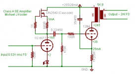
I just picked up a quad of nice 12B4s at the PO. I have also a pair of Transcendar 5K OPTs for a little weekend SET project...
I like the CCS driver a lot. It provides a more isolation from the cathode circuit signature, it gives better gain, better linearity of the driver, plus more available drive current. I plan to use the LED on the cathode as well as the CCS. I think I'll try a 6072 driver to start with.
Michael
PS another bonus of the CCS is good PSRR; no extra PS filter needed
PPS interesting anode structure on the 12B4
Attachments
Re: Great minds...
do you really need a gridstopper on the low gain 12b4a?
Michael Koster said:I just picked up a quad of nice 12B4s at the PO. I have also a pair of Transcendar 5K OPTs for a little weekend SET project...
I like the CCS driver a lot. It provides a more isolation from the cathode circuit signature, it gives better gain, better linearity of the driver, plus more available drive current. I plan to use the LED on the cathode as well as the CCS. I think I'll try a 6072 driver to start with.
Michael
PS another bonus of the CCS is good PSRR; no extra PS filter needed
PPS interesting anode structure on the 12B4
do you really need a gridstopper on the low gain 12b4a?
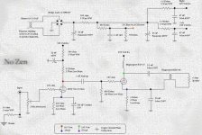
Mike, you have ultrapathed your 12B4A cathode to B+. Yet
the signal going into 12b4A grid is totally ground referenced.
Excellent PSRR with that input stage, but only when driving
into a ground referenced load...
Perhaps if replace the 1K2 with a series of 1K and then 180R.
To make a sample node with 1/Mu (1/6.5) power ripple. Bleed
your grid (through your 470K) to that point instead of ground.
Easy fix...
------------------------------oops--------------------------
Nevermind... Just realized what that does to the DC bias.
I need sleep.
zobsky:
"do you really need a gridstopper on the low gain 12b4a?"
Probably not. It's a habit. If I'm not intending to drive the grid positive, I usually put in a stopper to limit grid current. I have seen ringing due to small positive grid excursions in some cases. Maybe not on low-mu triodes, come to think of it... Some think grid stoppers degrade the sound; one day I'll take a closer look at the issue.
Ken:
Good observation. The schematic was originally for a direct photovoltaic (solar panel) powered amp where not much filtering is needed and I wanted constant current in the output stage. The ultrapath connection seemed elegant for this. Now I think I'll make it dual-powered, so will need to address the PSRR issue.
It will offer a good opportunity to experiment with some of the LW-ish ripple balancing systems you've been studying. I think you're on the right track, picking a place to tap the ripple voltage and send it back through inverted.
Thanks,
Michael
- Status
- This old topic is closed. If you want to reopen this topic, contact a moderator using the "Report Post" button.
- Home
- Amplifiers
- Tubes / Valves
- 12B4A SET - any critiques on this project?