That is correct. No buffered outputs for that series.
Anatech.
Would adding a buffer amp between the 3.1 and my Marchand XM-44 crossover help with the lower octave I feel like I'm missing?
Hi,
Yes, adding a suitable buffer would completely cure that issue. It would drive any sane solid state amplifier after that was added.
Watch that you don't just add a buffer chip. They need to be driven by a low Z source, so you would normally see an op amp driving a buffer chip with the buffer inside the feedback loop. A BUF634 would be an example of a good choice of buffer. You could also simply use a pair of NE5534, or a single NE5532 dual op amp. These will drive 600 ohm loads in case you are wondering why I picked a couple old chips. Modern ones would be an LME49710 (single) or LME49720 (dual, but surface mount only I think).
-Chris
If you can still find them a single LM4562 (dual) will drive anything down to 600 ohms without difficulty. Another option would be a pair of OPA134s or 2134 (dual)... (all dips) I shouldn't think a BUF634 would be required unless you needed to drive really low impedances (basically below 600 ohms). The BUF should be used inside the op-amp's feedback loop some care may be required to avoid oscillation with high bandwidth op-amps.
Hi Kevin,
Absolutely!
A BUF634 in TO-220 preceded by a premium op amp makes a fine headphone amplifier. The OPAx134 ICs are my favorite FET input op amps, and should also be able to drive a solid state amplifier without any difficulty. Having said that, it is critical that the PCB for the added parts be a good design with proper supply bypassing. These new chips are FAST compared to the older chips I'm used to using.
-Chris
Hi,
Yes, adding a suitable buffer would completely cure that issue. It would drive any sane solid state amplifier after that was added.
Watch that you don't just add a buffer chip. They need to be driven by a low Z source, so you would normally see an op amp driving a buffer chip with the buffer inside the feedback loop. A BUF634 would be an example of a good choice of buffer. You could also simply use a pair of NE5534, or a single NE5532 dual op amp. These will drive 600 ohm loads in case you are wondering why I picked a couple old chips. Modern ones would be an LME49710 (single) or LME49720 (dual, but surface mount only I think).
-Chris
Can you recommend a pre built unit I can purchase?
Your talking to a guy who builds everything himself. All I can suggest is that you do a search on Ebay. There is probably something available.
-Chris
I know. I wish I had your skills. I see a Burson AB-160 on ebay for $295.00. Maybe that will work.
If you can still find them a single LM4562 (dual) will drive anything down to 600 ohms without difficulty.
LM4562 is an active part. Why wouldn't one be able to find them?
Hi Chris,
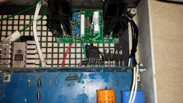
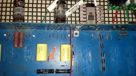
The S2530 pass transistor in my modified Counterpoint SA-3 finally blew up. Luckily I had on hand a K&K HV shunt regulator that I was going to try out. I installed it after the series power resistor, and ran the reg. output straight to the plate resistors, bypassing the 3 lytic caps.
The results are quite dramatic. The transients and imaging are much improved, and the bass is tight and clean and well extended. The phono stage sounds great too.
I'd be quite happy to live with this one if something happened to my reference modified Counterpoint SA-5000.
Regards Paul.
Hi Paul,
You won't believe what I have done with the SA-5000. I had to completely redesign the power supply. Everything from the rectifier / filter section, through the regulator and even down to the local bypass areas. I've done two so far and their owners are quite happy with their "new" preamplifiers.
What you did with the SA-3.1 is similar to what I have on the drawing board, and your results are perfectly believable. I think that I'm going to stick with series regulation for it though. A completely new PCB will be built for the regulators. The SA-3.1 was particularly nasty as far as power supplies go. If you looked at the actual voltages and current draw, then compared that to transistor datasheets, you would discover that the operating point was actually sitting on the SOA curve boundary for most transistors. We are talking about the robust ones. Power supply failure is merely a matter of time for this model.
I'm really pleased to hear you repaired your preamp properly, and it can now deliver the sound quality it is capable of. At this moment in time, you probably have the very best SA-3.1 that exists. You deserve to be very proud of your work. There was no repairing that design, and your solution is viable.
How much heat does your shunt regulator throw off? Just curious. The amount of heat I calculated way back when pushed me off a shunt regulator design. I think I was looking at 15 watts or so (probably higher but I can't remember exactly).
-Chris
Thanks Chris for your encouraging comments. This forum is amazing!
I was drawn to the shunt reg. due to the popularity of the Salas HV reg, and the fact that the late Allen Wright favoured this type of regulation, and his Super Reg is still available from Vacuum State.
I calculated 6.6 W. for the current source heatsink, and 9.9 W. for the shunt reg. HS, which equates to about 60-70 degrees C. for the respective heatsinks., about the same as the Salas reg. All the photos I've seen of similar regs use about 2.5" heatsinks. I will play around with the tube operating points to try to reduce the heat load. Also, the top cover may dissipate some of the heat.
I still prefer the the SA-5000, as it sounds more natural, and the build quality is vastly superior.
Cheers Paul.
Hi Paul,
Sounds like a plan. As long as your HT levels are stable and noise free, I can't see anything wrong with how you did this. Your dissipations look realistic too. When you have the time, could you post a picture of what your SA-3.1 looks like now inside?
The SA-5000. If you think it sounds good now ...
If you ever decide to work on yours, please, please, please. Use only parts that fit properly, and be careful of the lead diameters as the board uses plated through holes. If your unit has high voltage stability problems, it requires the redesign work I've done. Cross that bridge when you get to it. The work is very involved, but it still uses most of the original component locations and traces. This also reduces background noise noticeably. I also fix a problem where the phono tubes burn out. That was a tricky one to find.
I'm afraid that this is a true redesign and I'm doing each unit myself. This is especially true for you since you live in Oz. I do have the ability to run equipment at 220V~240V, but at 60 Hz. That wouldn't be a problem in your case. I hope your SA-5000 doesn't require this service, but the work is a big upgrade in sound quality even though it is mostly based in the scientific approach.
Best, Chris
Counterpoint SA-3 Upgrades
Hi Chris,
Judging by your earlier comments comparing stock and modded SA-5xxx's, the PSU mod for the SA-5000 must be impressive. It is great to see these formidable amps being improved. Your caution regarding reworking is noted, as it is so easy to damage the PCB tracks.
I wouldn't be in a position to ship my amp, as the cost is prohibitive. Taxes and customs charges apply on top of considerable postage costs, not to mention possible damage in transit.
Re the SA-3, time will tell if it is reliable. I would love to take it back to the shop where I bought it, and compare it to something costing $10,000.
Cheers Paul.
PS trouble posting pix, will email.
Hi Paul,
Yes, I expected the shipping costs would be pretty high. Too bad!
The rework is impressive. One of my clients was going to sell his. Not any more, it's staying put in his house.
I can post your picture for you if you want. It would be my pleasure in fact. I'm really curious to see how you mounted your new regulator.
I'd like to thank you for reporting on what you did to save your SA-3.1. These preamps can sound really, really good. Sadly, the total disaster that was his power supply designs saw the company fail (as it should have done under those circumstances). But these units are worth rebuilding and correcting the design faults, and one of the side benefits is much improved sound quality.
The one biggest threat I see for Counterpoint owners is the terrible hack service people out there. The number of really good technicians is dwindling, but they are out there! It's not worth taking these to "a guy that works cheap"! The cost of doing that can involve a unit that isn't repairable (never mind not worth it).
-Chris
Hi Mark,
Michael (Counterpoint) did all kinds of stupid things. The Plitron transformers ran hot and were often left loose in the chassis. What you need to do is keep the original transformer and redesign the power supply. That's a job I will be doing in the near future, I don't have any plans to sell PCBs. This is high voltage at high temperatures, and unless it is installed properly you're going to have problems. Sometimes component values need to be adjusted slightly.
Remember, this is going to be a new circuit board installed where there isn't a place to put it. The original regulators should be depopulated and wiring swung over to the new circuit. The new regulator will distribute the heat across more devices and into an improved heat sink. There will be improved ripple and noise rejection, and lower power wasted in the heater circuit. The power supply is a completely new circuit compared to the way the old one worked.
Anyway, it's high voltage, high temperature stuff and that needs respect. Installation of the components and entire PCB needs to be done correctly. Because everything in different Counterpoint models have been involved work, I can't see the average person doing this properly. No offence, I'm just going off what I see walk through my door and most isn't pretty!
-Chris
Hi Mark,
I use my SA-3 as a prototype to try out tweaks. I have been intrigued by HV shunt regs. due to the popularity of the Salas reg., and I purchased a kit from K&K Audio, which is similar. I have had this up and running for about six weeks now, and although it runs hot about 70deg.C, it has been performing well, and I actually prefer it to my modified SA-5000. It still has the same impressive sound stage and imaging, but is very clean and tight with better dynamics and incredible bass, as good as a friend's Emerald Physics tri-amped setup with twin 15" woofers per side. I am so delighted with the improved sound, I am working on a Vacuum State Super Reg to go in my SA-5000.
The old transformer is running hot also with the increased power requirements. Forget about all the mods that Alta Vista charged a lot of money for. All this great amp needed was a decent HV regulator.
Disclaimer:- I totally support Anatech's comments regarding caution when working on this equipment.
Hi ozdiyer,
The SA-5000 is one I have sorted completely. It does require some audio path modifications as well. The power supplies need some redesign in both the audio chassis and the outboard power supply unit. The secondary goal I had was to reduce the operating temperatures, which was met. The transformer now runs cooler as a result.
These preamps need a series regulator instead of a shunt. The transformer isn't really up for all that energy, so you have to drop the energy waste as much as possible. Besides, a series regulator can be as quiet as a shunt regulator. In addition, you need to have a good look at the SOA curves that your pass devices are running at. Especially with the SA-3.x preamps. The stock SA-3.x preamp is running right on the edge of the SOA curve for it's pass transistor, and any replacement will be running in the same point on that curve. Shunt regulators have the distinct disadvantage in that the total supply voltage appears across the power transistor.
-Chris
- Status
- This old topic is closed. If you want to reopen this topic, contact a moderator using the "Report Post" button.
- Home
- Amplifiers
- Tubes / Valves
- Counterpoint 3.1