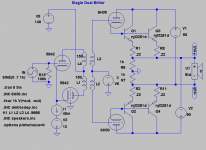
Got the compound triode/bjt idea from another thread that collapsed.
After some simming I have found the amp (working in AB with Iq=750mA) seems to be able to put out ca 30W/8ohm with below 1% distorsion. Above that I believe the triode limits the output and works as a "soft clipping" circuit.
I have just ordered the Slagle transformer for another balanced LCR-RIAA project but it would certainly be a good candidate here.
The 6H30 as driver seems too be the perfect candidate due to its good linearity at low voltages.
As I am no sand-wizard, please comment on eventual drawbacks to be expected.
Also this is Spice, it might not work at all IRL") !
!
Probably balancing the 6H30 will be a problem and also the warming up.
(Please "oldeurope", do not participate in this thread !)
After some simming I have found the amp (working in AB with Iq=750mA) seems to be able to put out ca 30W/8ohm with below 1% distorsion. Above that I believe the triode limits the output and works as a "soft clipping" circuit.
I have just ordered the Slagle transformer for another balanced LCR-RIAA project but it would certainly be a good candidate here.
The 6H30 as driver seems too be the perfect candidate due to its good linearity at low voltages.
An externally hosted image should be here but it was not working when we last tested it.
As I am no sand-wizard, please comment on eventual drawbacks to be expected.
Also this is Spice, it might not work at all IRL
!Probably balancing the 6H30 will be a problem and also the warming up.
(Please "oldeurope", do not participate in this thread
!)Attachments
Another way to abuse those thermaltrak diodes might be to modulate
the voltage of a cascode. Let each beta device (multiplying current)
have its own sink, far away from the heat of the guarding device.
Top half of the cascode dissipating most of the voltage and power.
The lower device can be its own oven to some stable temperature.
Raise the guard voltage to make it heat faster. Lower the guard to
prevent overheating beyond the desired operating point. We would
probably want to regulate for some specific quiescent current, that
both sides match, than attempt to regulate a specific temperature.
I don't know if Thermaltrak is relevant if you go by the current....
I think there is enough plate voltage at all times to accomodate a
bipolar cascode.
--------------------------------------------------------------------------------------
It hardly matters if you choose a 3281 NPN under the cathode, or
a 1302 PNP above the plate, except for the cathode bias... And you
have chosen to use a center tapped voltage reference anyway.
Only mention, cause modulating the cascode for thermal control
might be easier done with the guarding totem upside (pnp) down...
Hi kenpeter,
Thanks for your thoughts. Sorry to say, but I don´t understand anything of what you say. To complicated or far out for me. But you don´t need to explain as your, as I imagine, good ideas falls a little outside this thread.
I will not modify the initial concept and not complicate the sand-part, just want comments on the circuit as is.
But as you mention it, the diodes could be used. But I will in that case stick to simple temperature compensation.
Thanks for your thoughts. Sorry to say, but I don´t understand anything of what you say. To complicated or far out for me
. But you don´t need to explain as your, as I imagine, good ideas falls a little outside this thread. I will not modify the initial concept and not complicate the sand-part, just want comments on the circuit as is.
But as you mention it, the diodes could be used. But I will in that case stick to simple temperature compensation
.revintage said:Got the compound triode/bjt idea from another thread that collapsed.
...
(Please "oldeurope", do not participate in this thread
Don't panic, in the future I'll only take part in this forum if really neccessary.
...another thread that collapsed...
http://triodelington.blogspot.com/2007/10/triodelington.html
Darius
Lars, I don't know if this falls outside of the "willing to do" part, so my apologies in advance. Since the drive requirements are fairly modest, why use an interstage instead of RC coupling?
My own prejudices are not to run the output current through PN junctions, but I'll freely admit that it may be just superstition. I'm going to try to set up a version of the triode-bipolar Darlington as a common-cathode stage and see how the spectra compare to the "bare" tube, since no-one seems to have done this before.
My own prejudices are not to run the output current through PN junctions, but I'll freely admit that it may be just superstition. I'm going to try to set up a version of the triode-bipolar Darlington as a common-cathode stage and see how the spectra compare to the "bare" tube, since no-one seems to have done this before.
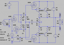
Sy, I don´t agree at all about caps versus iron. But let´s take that discussion elsewhere.
As the two proposed circuits are close to identical it should though be easy to convert between the two and do the evaluation between the Slagle and a pair of 1,5uF Mundorf silver/oil I have lying in my safe.
As I see the big difference using the iron is that it loads the drivers with nearly 40k(without secondary termination) instead of the resistors 18k at 20Hz. And this with B+ 140V instead of 440V.
But this isn´t the most important part of the circuit. It is still the triode/bjt compound and I don´t have a clue about how it will perform.
Please report back about yours measurements and findings.
As the two proposed circuits are close to identical it should though be easy to convert between the two and do the evaluation between the Slagle and a pair of 1,5uF Mundorf silver/oil I have lying in my safe
. As I see the big difference using the iron is that it loads the drivers with nearly 40k(without secondary termination) instead of the resistors 18k at 20Hz. And this with B+ 140V instead of 440V.
But this isn´t the most important part of the circuit. It is still the triode/bjt compound and I don´t have a clue about how it will perform.
Please report back about yours measurements and findings.
I'm going to try to set up a version of the triode-bipolar Darlington as a common-cathode stage and see how the spectra compare to the "bare" tube, since no-one seems to have done this before.
I tried this about 5 years ago. I put the idea and the schematic of an amp that I built on my web site back then, it is still there. This brought me so much hate e-mail from the vacuum tube purists that I abandoned the concept. I was not looking at this from an OTL perspective, I wanted a 45 tube that could put out 10 watts (in SE) and still sound like a 45. I got close but eventually blew up all of the BJT's that I had begged from the ON semi rep. I was running the "darlington" pair at 380 volts. This is close to the edge of the SOA on the BJT (secondary breakdown). A mosfet doesn't have the SOA limitation but I couldn't get them to sound good. Looking back now I think that the mosfets that I was using were huge non linear capacitors since they came from PC power supplies.
http://www.tubelab.com/SuperTubes.htm
http://www.tubelab.com/SuperTubeSE.htm
The problem that I see with this circuit is one of balance. The simulator assumes that all of the transistors will have the same hfe (beta) and it will stay constant. It also assumes that the tubes will have the same Mu. In reality they will not. The gain of the tube (Mu) is multiplied by the hfe of the BJT in this darlington like arangement, so little differences can become big offsets. I would put all of the transistors on a common heat sink and allow for some means of adjusting the offset. Test with a resistive load before attaching a speaker!
Hey Tubelab,
When I checked your links I remembered I had been there before. But had forgot. Hope you take up the work someday.
Interesting though that you have done quite a bit of testing. As I guessed, and you experienced , it is asking for trouble when using bjt for high voltages. So my idea was to turn the solution upside down and using low voltage and OTL.
I totally agree that DC-balance will be the main problem. To solve this I used a stable and and good matching dualtriode tube with low mu.
When I checked your links I remembered I had been there before. But had forgot
. Hope you take up the work someday.Interesting though that you have done quite a bit of testing. As I guessed, and you experienced
, it is asking for trouble when using bjt for high voltages. So my idea was to turn the solution upside down and using low voltage and OTL.I totally agree that DC-balance will be the main problem. To solve this I used a stable and and good matching dualtriode tube with low mu.
revintage said:Hi Wavebourn,
Have you actually tried the compound? Don´t think it will work at all with the suggested resistors. Do a sim and you will find out. Or you show us how it should be done!
Your choice: to sim well, or to ask transistors to commit suicide (George did already).
I am currently getting 120W from 6N6P.
About simming it is a course tool, which I said in my first post.
But if the sim shows it won´t work at all with the resistors in this particular circuit you must be a magician to make it work IRL.
So once again: Please show us, if you know how a circlotron arrangement around this compound should be done!
But if the sim shows it won´t work at all with the resistors in this particular circuit you must be a magician to make it work IRL
. So once again: Please show us, if you know how a circlotron arrangement around this compound should be done
!I think Waveborne is trying to tell you to add resistors from the cathodes of the output 6H30's to the respective output terminals. IE a resistor from the top cathode to the junction of R6 and R1, do the same to the bottom half. This helps stabilize the transistors.
I did add such resistors in my ancient design but it still blew up. The large (500) ohm resistor shown in my schematic stops the "suicide" due to SOA breakdown but kills the dynamics of the sound.
Now that 5 years have passed a lot more people are receptive to the use of silicon in tube amps. The DSP based design is still hard for most people to accept though. While working on that I did investigate some tubes that can handle fairly high currents at low voltages. I have also acquired some 600 ohm SE OPT's. Maybe it is time to try this again.
UH, 6 ma?
I'm going to try to set up a version of the triode-bipolar Darlington as a common-cathode stage and see how the spectra compare to the "bare" tube, since no-one seems to have done this before.
I would like to see what the plate curves of one of these "darlington" pairs looks like. There is still an old TEK 576 curve tracer in our lab at work. I think I would get a lot of questions if I tried to "curve" a vacuum tube though.
I did add such resistors in my ancient design but it still blew up. The large (500) ohm resistor shown in my schematic stops the "suicide" due to SOA breakdown but kills the dynamics of the sound.
it is asking for trouble when using bjt for high voltages. So my idea was to turn the solution upside down and using low voltage and OTL...... Hope you take up the work someday.
Now that 5 years have passed a lot more people are receptive to the use of silicon in tube amps. The DSP based design is still hard for most people to accept though. While working on that I did investigate some tubes that can handle fairly high currents at low voltages. I have also acquired some 600 ohm SE OPT's. Maybe it is time to try this again.
for 0.6V voltage drop current through 100 Ohm resistor will be 0.6 mA only
UH, 6 ma?
I'm going to try to set up a version of the triode-bipolar Darlington as a common-cathode stage and see how the spectra compare to the "bare" tube, since no-one seems to have done this before.
I would like to see what the plate curves of one of these "darlington" pairs looks like. There is still an old TEK 576 curve tracer in our lab at work. I think I would get a lot of questions if I tried to "curve" a vacuum tube though.
Sorry, 6 mA. Anyway, not a big deal against 30 mA for a tube, but I'd add some NFB by voltage.
I use 6N6P with IRFP450, in class A+C (I did not figure out how to bias them in AB thermal stable). This morning I started to breadboard 12L6 tubes with IRFP450, results will be later (had to work on a condenser microphone that I will need this weekends)
I use 6N6P with IRFP450, in class A+C (I did not figure out how to bias them in AB thermal stable). This morning I started to breadboard 12L6 tubes with IRFP450, results will be later (had to work on a condenser microphone that I will need this weekends)
revintage said:Hi Waveborn,
The problem was that you for some reason forgot to tell where you wanted to place the resistors
Sorry, I thought it is obvious.
- Status
- This old topic is closed. If you want to reopen this topic, contact a moderator using the "Report Post" button.
- Home
- Amplifiers
- Tubes / Valves
- Hybrid OTL Circlotron idea