I have been working on laying out a PC board for the big version of the Simple P-P. I have worked on it on and off for the past six months. I have come to the realization that two channels and a power supply will not fit on any reasonable sized PC board. Four octal output tubes with minimum spacing between them takes at least a 10 inch wide board, and that is ruling out fat bottled tubes like the KT88. I have started about 5 different designs, got frustrated and gave up. I think that the octal version of any type of Simple P-P will have to be mono blocks.
About two weeks ago I decided to put it on hold for a while and do something fun. I had a discussion with a friend about a "spud" amp a few days before a three day weekend. That resulted in a new design and a new PC board which was seen in another thread last weekend. I even got to crank up some tubes and make em glow. I had too much fun, so...
I took two more days off of work. There was the matter of the smaller version of the Simple P-P. I have two designs on my Tubelab 3 prototyping system. They both work, and are very similar except for the tube lineup. I took a guess and assumed that the EL84 version would be the most popular, and decided to lay out a PC board for it. Besides I have another reason for doing an EL84 board that I can't divulge yet.
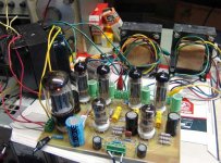
By Friday I had a good PC board design. Friday night, I made a PC board. Today I drilled it, and populated it. This evening I hooked it up to my power supply, and plugged in the first 12AT7. It lit up and the voltages were about right. Then I attempted to plug in the second 12AT7. Do you see the problem here?
About two weeks ago I decided to put it on hold for a while and do something fun. I had a discussion with a friend about a "spud" amp a few days before a three day weekend. That resulted in a new design and a new PC board which was seen in another thread last weekend. I even got to crank up some tubes and make em glow. I had too much fun, so...
I took two more days off of work. There was the matter of the smaller version of the Simple P-P. I have two designs on my Tubelab 3 prototyping system. They both work, and are very similar except for the tube lineup. I took a guess and assumed that the EL84 version would be the most popular, and decided to lay out a PC board for it. Besides I have another reason for doing an EL84 board that I can't divulge yet.
By Friday I had a good PC board design. Friday night, I made a PC board. Today I drilled it, and populated it. This evening I hooked it up to my power supply, and plugged in the first 12AT7. It lit up and the voltages were about right. Then I attempted to plug in the second 12AT7. Do you see the problem here?
Attachments
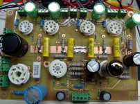
Is that a little issue of Chinese hole tolerance? I actually had a 9 pin PC mount socket that came with solder in one of the pin cups... I've been enjoying PCB design lately too, but my EL84 PCB is still in development. I'm still getting a feel for how much space I can leave between traces without screwing myself.
-Paul
-Paul
Well I decided that the tube WAS going into that socket since it wasn't much fun to change the socket. Application of excessive force only resulted in a broken tube. After a few other dumb ideas didn't work, I resorted to a PC board drill bit in a Dremel tool set on max speed. Zipped right through the substance that the Chinese call ceramic. Second 12AT7 installed and working.
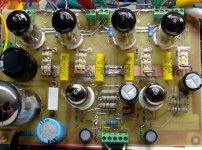
There was no B+ getting to the right channel OPT. It was an open trace in my low quality PC board.
Other than these two issues, the amp works very well. 15 WPC at 0.45% distortion. 16 watts however will get you 4%.
There was no B+ getting to the right channel OPT. It was an open trace in my low quality PC board.
Other than these two issues, the amp works very well. 15 WPC at 0.45% distortion. 16 watts however will get you 4%.
Attachments
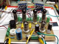
Here the amp is still running on a bench type lab power supply. This lets me pick the voltage that the amp likes the best. I decide that 320 volts is where I want to be.
I adjusted the global negative feedback to 6 db. This seemed to still leave the music alive, while tightening up the bass. I attached speakers and a DVD player, and rocked the house!
I adjusted the global negative feedback to 6 db. This seemed to still leave the music alive, while tightening up the bass. I attached speakers and a DVD player, and rocked the house!
Attachments
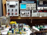
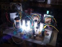
I take a guess as to what transformer will make 320 volts DC. In this case it is an Allied 6K56VG, which I hooked up. I put in a rectifier tube, and cranked it up. There is no choke in this amp, and there is no hum.
There will be some more testing, and more testing, and some serious tube rolling, before I can even dream of calling it a new product.
There will be some more testing, and more testing, and some serious tube rolling, before I can even dream of calling it a new product.
Attachments
have you thought of a modular design. rather than trying to fit it all one one board? Like a guitar amp...
That is where I am going. The plan is now a power supply board, and a single channel amplifier board. This takes away some of the "simple", but makes for a much better amp in the long run.
It's looking good George! Is it a Williamson type topology?
It is similar. There are no driver tubes, since the extra gain is not needed with EL84's, and it needs to be "simple". There is a common cathode gain stage directly coupled to the split load phase splitter, which directly feeds the output tubes. I tried several different topologies, but this works as good as any, and is the "simplest". I prefer LTP splitters, but I couldn't make one work without an additional tube. This amp is currently running in UL mode. I will try pentode and triode mode ASAP. I also will "test" some 6CW5's.
For some reason when I hear P-P I keep thinking P-P "Sweep". Of course I wouldn't be simple anymore then would it.
Not everything has to be "simple". I am working on a "universal driver board". I want a board that can drive up to 4 tubes with individual bias adjustments for each tube. It will be a fully differential design, and provide enough voltage swing and drive current for screen driven sweep tubes or 845's in A2. When you start thinking about big P-P amps you realize that the types of big tubes that are available varies a lot around the globe. Many sweep tubes that are common in the US don't exist elsewhere. Some big Russian tubes can't be found here, etc. The solution is to make a "universal" driver and power supply boards that can be used with off board mounted tubes. Back to the modular approach mentioned above.
could your board be adapted to the Red Light District?
I had to look up the schematic to the RLD, since my memory is not what it used to be. The two amps are very similar. I currently have seperate bypassed cathode resistors for each output tube to ease the tube matching requirements. The rest looks the same except for the resistor values. I find that I can get plenty of drive and the phase stays 180 degrees out to hundreds of KHz running the 12AT7 at 285 supply volts, but considerably higher current. I haven't tried a JJ yet though.
A bunch of LED's would take up a lot of board space, but an external LED board could be wired in easilly. I have a big box full of old LED's around here somewhere, I may try it. If I remember right they may be green though.
It is similar. There are no driver tubes, since the extra gain is not needed with EL84's,
Yes of course. I figured since it's one 12at7 per channel. Your defiantly on the right track I think. That topology is simple, but gives excellent results. Your tube selection is a good one too. And tube rectification, what more could one ask for.
")
Todays experiments were to make it bigger, bigger is better, right? Really, the amp isn't bigger, just the transformers. I replaced the (too) little Edcors with some guitar amp transformers that I have, since I noticed some saturation effects when playing it loud. I replaced the power transformer with a bigger one. The OPT's do not have a UL tap, so it is triode or pentode mode. Triode mode gives 8 watts, pentode gives 18. No one else is home, so pentode is chosen and Ozzie is in the CD player. This thing rocks, and does Ozzie well, Metallica too.
I tested some 6CW5's. They give about the same power as EL84's but need far less B+ voltage and about half the load impedance. No listening tests yet.
This Simple P-P amp contains no silicon. The driver board proto has CCS chips and mosfets (multiple PowerDrives). I haven't had time to finish the prototype yet.
I tested some 6CW5's. They give about the same power as EL84's but need far less B+ voltage and about half the load impedance. No listening tests yet.
"universal driver board". thats a really interesting idea would love to see how it develops
This Simple P-P amp contains no silicon. The driver board proto has CCS chips and mosfets (multiple PowerDrives). I haven't had time to finish the prototype yet.
Attachments
This is looking like a great project. As for "not everything having to be 'simple'" for the octal simple PP, sounds to me like you are going with two levels of project: Simple PP for EL84 and perhaps "Tubelab PP" for the more advanced (higher performance?) octal version. This sounds like a great way to go to me.
I have been itching to build some octal mono block PP amps. I have got to wait a few months anyway as I am about to move house so I am VERY interested in the concept of separate driver board with off board mounted valves when it gets developed.
Great work Tubelab!
I have been itching to build some octal mono block PP amps. I have got to wait a few months anyway as I am about to move house so I am VERY interested in the concept of separate driver board with off board mounted valves when it gets developed.
Great work Tubelab!
OK, SY you put me up to this.
I got to thinking about putting some LED's in the cathode circuit of the output tubes. I looked around here but couldn't find enough LED's that were all of the same kind. Then I remembered some white LED's that a friend had given me that were made for the flash in a camera phone.
These were surface mount creatures and they were not made for continuous duty. I didn't have too many of them either. I soldered some wires on one and connected it to a power supply in constant current mode. First off, they were BRIGHT! The voltage across one remains pretty constant once the current is above 20 mA. I cranked that one up to 150 mA and it didn't fry, but it got pretty hot after about 10 minutes. I cranked the hot LED to 200 mA and it was still alive. OK so far so good. The voltage was 3.4 to 3.5 volts. I measure 10 volts on the cathodes of my 7189A's so 3 in series should be about right.
Next, I needed to put 3 of them in series and heat sink them. I hand carved 5 PC boards made of some ceramic material, mounted 3 LED's on each and tested them. I picked the 4 closest ones, based on forward voltage drop. I measured and plotted the V/I curve for all 4 units in 10 mA increments from 10 mA to 100 mA. From this curve I computed the dynamic resistance for the LED string. The resistance is non linear up to about 40 mA but remains a very constant 5 ohms from 40 mA to 100 mA. This is good.
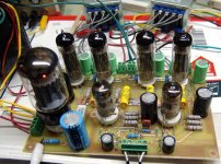
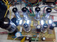
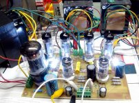
I removed the cathode resistors and their bypass caps from the PC board. I put one of the LED modules in the place of each cathode resistor. I can run each output tube individually on its own LED string, or run a jumper wire from cathode to cathode to run one channel (two tubes) on a parallel pair of LED strings.]
Here is a photo of the modified PC board.
I got to thinking about putting some LED's in the cathode circuit of the output tubes. I looked around here but couldn't find enough LED's that were all of the same kind. Then I remembered some white LED's that a friend had given me that were made for the flash in a camera phone.
These were surface mount creatures and they were not made for continuous duty. I didn't have too many of them either. I soldered some wires on one and connected it to a power supply in constant current mode. First off, they were BRIGHT! The voltage across one remains pretty constant once the current is above 20 mA. I cranked that one up to 150 mA and it didn't fry, but it got pretty hot after about 10 minutes. I cranked the hot LED to 200 mA and it was still alive. OK so far so good. The voltage was 3.4 to 3.5 volts. I measure 10 volts on the cathodes of my 7189A's so 3 in series should be about right.
Next, I needed to put 3 of them in series and heat sink them. I hand carved 5 PC boards made of some ceramic material, mounted 3 LED's on each and tested them. I picked the 4 closest ones, based on forward voltage drop. I measured and plotted the V/I curve for all 4 units in 10 mA increments from 10 mA to 100 mA. From this curve I computed the dynamic resistance for the LED string. The resistance is non linear up to about 40 mA but remains a very constant 5 ohms from 40 mA to 100 mA. This is good.
I removed the cathode resistors and their bypass caps from the PC board. I put one of the LED modules in the place of each cathode resistor. I can run each output tube individually on its own LED string, or run a jumper wire from cathode to cathode to run one channel (two tubes) on a parallel pair of LED strings.]
Here is a photo of the modified PC board.
Attachments
The amp is still wired in pentode mode. Power is still 17 watts but the distortion has decreased to 3% at 17 watts. Connecting the two cathodes together raises the distortion to 4.5%. The same effect was noticed at 5 watts. Distortion was 0.4% without the jumper, and 0.97% with the jumper. I removed the jumper. The LED's are bright, but the light is constant even into clipping except for very low frequencies like 5 Hz where they blink like crazy when the amp clips hard.
Attachments
I hooked up the CD player and speakers and cranked it up. I must state that the cathode bypass caps (now removed) were cheap junk (all I could find at the time). The bass and transients were remarkably more vivid. It seemed that the mids and the sound stage were more obvious too.
I only had about a half hour to listen to it, but I like it. Just 2 weeks ago if someone would have told me that I would be listening to a P-P amp in pentode mode and liking it, I wouldn't have believed them. Maybe the 3 year episode of the SE fever is subsiding.
I only had about a half hour to listen to it, but I like it. Just 2 weeks ago if someone would have told me that I would be listening to a P-P amp in pentode mode and liking it, I wouldn't have believed them. Maybe the 3 year episode of the SE fever is subsiding.
Attachments
- Status
- This old topic is closed. If you want to reopen this topic, contact a moderator using the "Report Post" button.
- Home
- Amplifiers
- Tubes / Valves
- Simple P-P 84 proto