I had an email conversation with someone who was interested in a spud amp. What is a spud amp? The usual definition is an amp that uses one tube per channel. It comes from the phrase "one tuber" which was shortened to "tuber" which is another word for a potato, and so is "spud". Somehow the name stuck.
The emailer asked if I had tested any of the spud amps on the market. I explained that I rarely see other peoples amps any more since I just don't have time to do repairs or mods. Then he asked "Why doesn't Tubelab do a spud?" Well this question was asked two days before I had a three day weekend, so I decided to think about it.
There are a few spud amps on the market currently. Most either use a dual dissimilar triode like the 6DN7 or 6EM7 to deliver 1 to 1.5 WPC, or a single high gain pentode like the 6CL6 or 12GN7 to deliver 0.5 to 2 watts. A triode - pentode like the 6BM8 could be used as well.
I decided that if I was going to do a spud it would be different. First it must be simple, really simple. Second, it must be useful to me. I could use a small amp for my computer, but I need more than 1 or 2 watts. Third, it must be small. Fourth, it must be cheap. And last, it MUST sound good. For it to be a true spud, there can be only two tubes.
Now that I have defined the amp, can it be built? Time for some experiments. It was the fourth of July, so a little fireworks may be in order. I had been testing several different output tubes in a tired old Simple SE board to see if which tubes to keep, and which tubes to wholesale. I decided to use the same PC board to test some multi section tubes. How? Well we need to answer the question "Is it possible to build an amp entirely with clip leads?" I would have said NO before I did this!
Do you believe that this actually works, and sounds good too!
Attachments
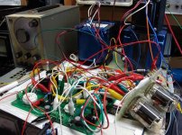
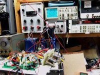
Here is a photo of the whole setup. The scope shows input (bottom) and output (top) of one channel. The audio analyzer shows 1.6% distortion at 2 watts. Clipping begins at 3.5 watts in triode and 5.5 in UL with the "big" tubes (triode - pentode). I can plud a set of dual dissimilar triodes into the same sockets (with some component changes) for far less power.
I got through the whole day on July 4th and didn't explode anything. I did see some tubes glowing, and some that flat didn't work. But the "furball" that you see here just works! No tendency to oscillate at all, and it sounds good too. Now it I can only make it look good.
I got through the whole day on July 4th and didn't explode anything. I did see some tubes glowing, and some that flat didn't work. But the "furball" that you see here just works! No tendency to oscillate at all, and it sounds good too. Now it I can only make it look good.
Attachments
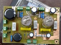
Remember the design criteria, small, simple, useful, sounds good, low cost. I got the sound down right, which is usually the first thing to work on after you solve the "it doesn't work" stuff. I needed to design a PC board that was small. It had to be easy to build, Simpler than a Simple SE, and work as well as the "furball".
I spent most of Saturday in front of the computer working on the layout. By evening I had a prototype quality board ready to be made. The process to make a PC board involves some nasty chemicals that must be used in the dark, followed by cooking up a plate of acid on the stove. I waited till Sherri was asleap for that one. Finished this part late Saturday night.
Sunday afternoon I had to drill all the holes in the board, and then it was ready for "stuffing", the process of soldering in all of the parts.
The photo shows the completed board. It occupies less area than a music CD. The PC board is 4 inches by 6 inches.
Attachments
")
From a Japanese website, using two 6LU8. Here's how you should package that amp:
The full link:
http://homepage3.nifty.com/softone/offmeet/2007/OFF070108t.htm
An externally hosted image should be here but it was not working when we last tested it.
The full link:
http://homepage3.nifty.com/softone/offmeet/2007/OFF070108t.htm
This Spud amp reminds me of the Mighty Midget, by Pete Millet. That one also uses a compactron.
http://www.pmillett.com/midget.htm
http://www.pmillett.com/midget.htm
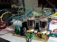
The board was populated with the same component values that were used in the "furball". I wired it up using the small 5K ohm Edocr OPT's in UL mode since they were more in line with the project goals. I also used an Allied 6K56VG transformer since I had one on my bench. It produces slightly more voltage than the power supply used with the "furball".
The amp worked on the first try with no tweaking. Tube dissipation was slightly over spec, but this was expected since I had planned for 300 volts of B+ and now had 320. No glow was visible in a dark room even after 4 hours of operation.
The amp measured quite good. Distortion was 3.05% at 5 watts, 0.88% at 1 watt. Clipping begins at 5.5 watts and 5% distortion is reached at 7.1 watts. Frequency response is 19Hz to 61 KHz at 1 watt. Power will be reduced somewhat when the tube is re-biased to a cooler operating point.
I listened to it for several hours last night. It sounds quite good. OPT saturation can be heard when playing techno or other bass heavy music at high volume. This can be fixed with larger OPT's, but that is not in line with the small and cheap goals. I plan to experiment a little further with this amp next weekend.
This was a three day diversion from my other projects. It was fun, and I didn't even blow anything up. I will stuff the entire amp into some sort of unique cabinet at a later date. Jose, the Kirin can is absolutely cool, but how to I put a flat PC board in a round can? The first step is to find a smaller power transformer.
This could become a new Tubelab PC board if there is enough interest. The board is smaller, so it would be slightly cheaper, depending on quantity (PC board houses charge a fixed artwork - tooling charge). My guess is that the whole amp could be built for under $200, not counting the enclosure. It is really a Simpler SE.
Is there any interest? Spud anyone? I will post the schematics once I actually have one. I kind of made this up as I went along.
Attachments
I believe the spud amp is one stage and not necesarily cheap.
The Gordon Rankin Simple 84 is an spud amp
http://db.audioasylum.com/cgi/m.mpl?forum=magnequest&n=426&highlight=el84+rankin&r=&session=
best regards Jaime
The Gordon Rankin Simple 84 is an spud amp
http://db.audioasylum.com/cgi/m.mpl?forum=magnequest&n=426&highlight=el84+rankin&r=&session=
best regards Jaime
A few guys over on www.audiokarma.org also are building a very low cost spud amp (target 150.00) with a 6LU8. It'll be a P2P design and they are making it very modular to allow some personal customization. It might be interesting to compare the two spud amps and do a little cross-board collaboration if there are improvements to be made on either.
If anyone is interested, their amp can be found here, http://www.audiokarma.org/forums/showthread.php?t=163886 and I know squidward quite well, in fact I think he is a member here.
I believe the schematic is quite similar to the RH84 with modified values for the tubes being used.
If anyone is interested, their amp can be found here, http://www.audiokarma.org/forums/showthread.php?t=163886 and I know squidward quite well, in fact I think he is a member here.
I believe the schematic is quite similar to the RH84 with modified values for the tubes being used.
I was not aware of the Audiokarma thread. I read it but can not see the schematics since I am not a registered member of that forum. I can imagine that it is similar since we are using essentially the same tube. I started with the Simple SE schematic, and left out the CCS IC, but added plate to plate feedback. This amp was developed around a 6LR8 (actually 21LR8's since I have a bunch). The 6LU8 and the 6LR8 are the same tube with a different number of pins.
I saw mention that the 6LU8 was a 12AT7 and a 6AV5 in the same bottle. This is not true. The 6LU8 may bias up similar to a 6AV5, but the maximum ratings are more like a 6V6. There was a reference to my 6AV5 testing implying that the 6LU8 could handle something similar. I can tell you that the 6LU8 can run over spec some what, but not at the levels that a 6AV5 can handle. The plate is just not big enough and there are no heat radiating wings.
There was some question as to the 6LU8's capability in UL with the Edcor OPT. This does work well and is exactly how I am using it. The screen grid is rated for 300 volts, and I haven't been above that rating yet. I don't think that it is necessary.
So am I. Either those TV commercials weren't that long ago, or I am even older than I realize.
I saw mention that the 6LU8 was a 12AT7 and a 6AV5 in the same bottle. This is not true. The 6LU8 may bias up similar to a 6AV5, but the maximum ratings are more like a 6V6. There was a reference to my 6AV5 testing implying that the 6LU8 could handle something similar. I can tell you that the 6LU8 can run over spec some what, but not at the levels that a 6AV5 can handle. The plate is just not big enough and there are no heat radiating wings.
There was some question as to the 6LU8's capability in UL with the Edcor OPT. This does work well and is exactly how I am using it. The screen grid is rated for 300 volts, and I haven't been above that rating yet. I don't think that it is necessary.
"This Spud's for you" SY is old enough to get it.
So am I. Either those TV commercials weren't that long ago, or I am even older than I realize.
Hi George,
This is awesome.
Thank you very much for dedicating so much time to DIY tube audio. This spud looks like the perfect computer speaker amp.
Since I don't need 50+ Watts on my computer this seems well suited.
I am sure it works equally well with an iPod and a set of small bookshelf speakers if you don't need large volumes.
Are you willing to share the schematic?
Cheers,
Martin
PS: I always enjoy the tubelab posts, but no fireworks on July 4th seems odd.
but no fireworks on July 4th seems odd.
Seemed odd to me too. Our neighborhood usually sounds like a war zone on the 4th, but it was relatively quiet. I guess that no one has money to burn (or blow up) this year.
I have a 6DN7 amp and it sounds fantastic.
I actually thought about this for a while, and one of the reasons I chose the 6LR8, is that a 6GF7 will drop right into the same socket. The bias resistor must be changed, and of course the screen grid isn't there so that pin is NC. It worked on the "furball" but I haven't tried it yet on the PC board.
We had a good 4th here,The usual 'warzone' like atmosphere.
Just looking at Pete's "Mighty Midget" schematic:
http://www.pmillett.com/file_downloads/midget_sch.pdf
It's interesting what he's done with the G3/suppressor grid of the first stage,and the LED's. It's elevated a bit above the cathode. Curious.
Just looking at Pete's "Mighty Midget" schematic:
http://www.pmillett.com/file_downloads/midget_sch.pdf
It's interesting what he's done with the G3/suppressor grid of the first stage,and the LED's. It's elevated a bit above the cathode. Curious.
Jef at AbraxasAudio did a 6197 Spud that sounded quite nice.
http://home.att.net/~abraxasaudio/projects/6197-spud1/6197-spud1.html
http://home.att.net/~abraxasaudio/projects/6197-spud1/6197-spud1.html
DigitalJunkie,
I am trying to make sense of the "Mighty Midget" schematic with my limited knowledge.
Is R1 responsible for some sort of negative feedback? I have never seen a direct connection between anodes of different stages (or at least I am not aware of having seen that).
Is someone willing to elaborate on that?
The zener diode plus LED string is interesting although I do not completely understand the purpose of that arrangement - I guess that means back to the books for me.
Martin
Think of them as three stacked voltage sources instead of three independent supplies each returned to earth. R1 performs its normal function of referencing grid to ground. My guess is a clever way to utilize one bias current to drive the diodes deep into their linear impedance regions. A true paranoid would have topped the stack with a CCS though.
It's interesting what he's done with the G3/suppressor grid of the first stage,and the LED's. It's elevated a bit above the cathode. Curious.
The operation of this circuit was explained in an article in AudioXpress magazine. For those who do not subscribe, the article is on their web site.
http://www.audioxpress.com/magsdirx/ax/addenda/media/millet2903.pdf
The short story:
The first pentode in the 6T10 is intended for operation in a circuit where both G1 and G3 control the flow of current. This is a special type of tube called a dual control pentode. Pete did not need the dual control aspect, so he found the voltage on G3 that resulted in the best linearity. He generated this small voltage and the cathode bias voltage using LED's. An LED functions like a low voltage zener diode. A 100 volt zener diode is added to the string to stabilize the screen voltage.
Is R1 responsible for some sort of negative feedback? I have never seen a direct connection between anodes of different stages (or at least I am not aware of having seen that). Is someone willing to elaborate on that?
The plate to plate resistor is indeed a negative feedback path. This is not something new. In fact it is something old. Plate to grid feedback was first outlined in O.H. Schade's article "Beam Power Tubes" in 1938. This article is essentially the introduction of the 6L6. The (output) plate to (driver) plate connection does the same thing, but eliminates the capacitor. This particular method of feedback has the advantage of making a pentode look like a triode with almost pentode power output. It usually requires a driver with a relatively high output impedance like a pentode. It can be used on some triode drivers, but doesn't work on others. It does work on the 6LU8 and 6LR8, and I am using it on my board. The resistor seen hanging off of the red clip lead in the "furball" is the feedback resistor.
The O.H Schade article can be found here. It is somewhat thick and full of math and other hard to understand stuff. The feedback information is at the very end.
http://www.one-electron.com/Misc_Docs.html
- Status
- This old topic is closed. If you want to reopen this topic, contact a moderator using the "Report Post" button.
- Home
- Amplifiers
- Tubes / Valves
- Spud anyone?