Hello,
I have built, for my Stax headphones, the amplifier described at http://www.bonavolta.ch/hobby/en/audio/hdgsta.htm
(diagram attached).
The thing makes music, and rather well, but I am not completely sure that everything is right:
For one thing, the oscilloscope shows higher amplitude on one branch, and the trimmer doesn't adjust beyond a certain level that I don't find "enough" (say 5% amplitude difference, otherwise gross distortion).
And the sound has something strangely disturbing that I cannot define well, but that has me develop a headache after an hour of listening.
Oscillation? Couldn't detect any on the 'scope or with the "AM radio" method, but who knows...
And then, maybe it can sound even better.
So here's the questions.
(Just primary pattern-matching.
Thanks for your patience, I am not very experienced with tubes (barely more with transistors...), but I'll learn if tought well )
)
The circuit looks like a phase splitter with each "phase" driving an output stage for one of the stators (of course Staxes work in balanced mode, and, fwi understand, the few schemas I've seen around all apply this same basic architecture).
"My" splitter looks like a "cross-coupled" structure, except that the output from the first triode on the Stax diagram is from the anode, instead of being a cathode-follower (like described in tubecad or bonavolta or other rare drawings of this Van Scoyoc thing.)
Is it supposed to work anyway (and the (dynamic?) inbalance I observe is just supposed to be there)?
If not, and if I decide to move the "cross" to the cathodes, should the feedback be applied somewhere else?
Should anything else change?
Thanks in advance,
pilli
Last piece of info: my output tubes are 6S4 because I had started one of Gilmore's designs, then found this one easier to start with.
Also, my coupling caps are 1,5uF, because "those were lying around when I reached for 400V caps".
Don't think this has an influence on the input stage.
I have built, for my Stax headphones, the amplifier described at http://www.bonavolta.ch/hobby/en/audio/hdgsta.htm
(diagram attached).
The thing makes music, and rather well, but I am not completely sure that everything is right:
For one thing, the oscilloscope shows higher amplitude on one branch, and the trimmer doesn't adjust beyond a certain level that I don't find "enough" (say 5% amplitude difference, otherwise gross distortion).
And the sound has something strangely disturbing that I cannot define well, but that has me develop a headache after an hour of listening.
Oscillation? Couldn't detect any on the 'scope or with the "AM radio" method, but who knows...
And then, maybe it can sound even better.
So here's the questions.
(Just primary pattern-matching.
Thanks for your patience, I am not very experienced with tubes (barely more with transistors...), but I'll learn if tought well
)The circuit looks like a phase splitter with each "phase" driving an output stage for one of the stators (of course Staxes work in balanced mode, and, fwi understand, the few schemas I've seen around all apply this same basic architecture).
"My" splitter looks like a "cross-coupled" structure, except that the output from the first triode on the Stax diagram is from the anode, instead of being a cathode-follower (like described in tubecad or bonavolta or other rare drawings of this Van Scoyoc thing.)
Is it supposed to work anyway (and the (dynamic?) inbalance I observe is just supposed to be there)?
If not, and if I decide to move the "cross" to the cathodes, should the feedback be applied somewhere else?
Should anything else change?
Thanks in advance,
pilli
Last piece of info: my output tubes are 6S4 because I had started one of Gilmore's designs, then found this one easier to start with.
Also, my coupling caps are 1,5uF, because "those were lying around when I reached for 400V caps".
Don't think this has an influence on the input stage.
Attachments
Wow, there's some very odd things about this circuit. The second stage tubes have only 50V across them. Stage current is VERY low. This is not a low distortion amplifier.
Your observation is correct, they have the first two stages connected as a cross coupled cascode instead of the "normal" biological amp.
Can you provide a DC voltage map for your build? Are the voltages symmetrical?
Your observation is correct, they have the first two stages connected as a cross coupled cascode instead of the "normal" biological amp.
Can you provide a DC voltage map for your build? Are the voltages symmetrical?
It is a very unusual design and is unlike any other that I've ever seen. I agree, the way it's drawn looks at first glance like a Van Scoyoc splitter but studying it more makes me think it's a cross-coupled SRPP. I don't think it would help to turn it into a true Van Scoyoc because then you would lose gain. In any case, a Van Scoyoc is basically unbalanced and wastes tubes. That's why it's rare.
I'm unfamiliar with Stax headphones but, from the description in the article, I guess they're electrostatic?
I do agree with the author that some form of grounding would seem better at the junction of those 100uF cathode bias bypass capacitors. I also feel that the 300k plate loads for the second 12AT7 are very high and could be a cause of serious noise.
Thanks for these quick replies!
Ray,
Yes, those are electrostatic "headspeakers" (ideal application for tubes, I guess.)
I have used them for a while with simple step-up transformers and I did not get that headache (I mean, I don't think it just "headphone tiredness") that makes me suspect my build.
SY,
The voltages I get are "consistent" with the diagram
I attached a picture with some voltages I remember (writing from the office , I'll measure more this evening)
Remarks:
- The DC voltages I get are symmetrical, or can be made quite symmetrical with the trimpot; but then the sinusoids are much less symmetrical (I can post some images later...) in amplitude.
I went for a compromise, also based on the source site:
"...the adjustments can be done statically or dynamically.
(...) in an unbalanced design, it is better to adjust the trimmer so that the "lower" branch has a slightly higher voltage. In this way, the amp is adjusted for DC but also for AC.
With a sinusoidal generator and oscilloscope, it is pretty easy to adjust the trimmer so that each branch of the final stage input receives a signal in phase opposition but identical amplitude."
- Output voltages react well to changes to B+, so I get them to 0V
- I was surprised how silent it is, given my building-skills are far from impeccable. Maybe noise balances out.
- I did put the resistor between the back-to-back caps.
- I have slightly lower supplies (components I had available)
In any case, would you say that a simple mistake in drawing the diagram is ruled out?
I mean, it's different enough from a "normal" cross-coupled phase splitter to say that it is not supposed to be wired differently?
(In that case it is worth trying to understand if and how it works...)
(I'll be back in a few hours with real data from the scope.)
_
Ray,
Yes, those are electrostatic "headspeakers" (ideal application for tubes, I guess.)
I have used them for a while with simple step-up transformers and I did not get that headache (I mean, I don't think it just "headphone tiredness") that makes me suspect my build.
SY,
The voltages I get are "consistent" with the diagram
I attached a picture with some voltages I remember (writing from the office
, I'll measure more this evening)Remarks:
- The DC voltages I get are symmetrical, or can be made quite symmetrical with the trimpot; but then the sinusoids are much less symmetrical (I can post some images later...) in amplitude.
I went for a compromise, also based on the source site:
"...the adjustments can be done statically or dynamically.
(...) in an unbalanced design, it is better to adjust the trimmer so that the "lower" branch has a slightly higher voltage. In this way, the amp is adjusted for DC but also for AC.
With a sinusoidal generator and oscilloscope, it is pretty easy to adjust the trimmer so that each branch of the final stage input receives a signal in phase opposition but identical amplitude."
- Output voltages react well to changes to B+, so I get them to 0V
- I was surprised how silent it is, given my building-skills are far from impeccable. Maybe noise balances out.
- I did put the resistor between the back-to-back caps.
- I have slightly lower supplies (components I had available)
In any case, would you say that a simple mistake in drawing the diagram is ruled out?
I mean, it's different enough from a "normal" cross-coupled phase splitter to say that it is not supposed to be wired differently?
(In that case it is worth trying to understand if and how it works...)
(I'll be back in a few hours with real data from the scope.)
_
Attachments
Understand that the waveforms might well be unsymmetrical- the 2nd harmonic distortion of each side is likely to be quite high, the idea being that it cancels in the differential output. That will be difficult to verify without a differential input to your scope, but we might be able to eyeball some stuff from scope photos and get an idea.
Further in the "what were they thinking?" department, one notes that the feedback is nearly ineffective, maybe 4 or 5 dB at the most, maybe even less. Why bother?
Further in the "what were they thinking?" department, one notes that the feedback is nearly ineffective, maybe 4 or 5 dB at the most, maybe even less. Why bother?
...phew! this took some time!
(VERY careful poking probes into my p-to-p mess!!)
So here is what I can measure, if I can take some more time from you guys:
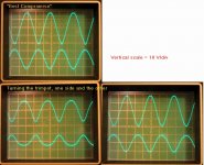
This image is at the two coupling capacitors "input side" (that is "before" the cap)
(Refer to the diagram of my first post.)
Input is a sine wave at 1KHz, 2Vpp.
The upper trace is the upper branch, out of pin 1 of the second stage. The lower trace is out of pin 6.
As you can see, there's no way the amplitude of the lower branch can increase.
In the "best compromise" the upper trace is about 38Vpp, and the lower less than 24Vpp. And both visibly distorted.
If I turn the trimpot, it distorts, but the two amplitudes never match.
In the "best compromise", the DC in the second-stage plates are:
"upper" = 90-95V
"lower" = 95-105V
The first stage plates (I wasn't sure of the earlier measurements) are worse than what I thought: upper "input" plate is at 68V, lower at 71V, which means, as SY pointed out, that the second stage only has a tiny A-K voltage across it...
(VERY careful poking probes into my p-to-p mess!!)
So here is what I can measure, if I can take some more time from you guys:
This image is at the two coupling capacitors "input side" (that is "before" the cap)
(Refer to the diagram of my first post.)
Input is a sine wave at 1KHz, 2Vpp.
The upper trace is the upper branch, out of pin 1 of the second stage. The lower trace is out of pin 6.
As you can see, there's no way the amplitude of the lower branch can increase.
In the "best compromise" the upper trace is about 38Vpp, and the lower less than 24Vpp. And both visibly distorted.
If I turn the trimpot, it distorts, but the two amplitudes never match.
In the "best compromise", the DC in the second-stage plates are:
"upper" = 90-95V
"lower" = 95-105V
The first stage plates (I wasn't sure of the earlier measurements) are worse than what I thought: upper "input" plate is at 68V, lower at 71V, which means, as SY pointed out, that the second stage only has a tiny A-K voltage across it...
Attachments
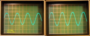
...and this is what comes at the outputs.
Some difference in amplitude, some distortion too, I would say.
(edit: maybe it is clipping with 2Vpp input...? I'll try with a lower input.)
I only have one probe with 10x so I had to take them one at the time...
The left image is the "lower" branch, looking like 320 Vpp.
The right image is the "upper" branch, at about 400 Vpp.
...hey, are they in phase?
Should they be?
Some difference in amplitude, some distortion too, I would say.
(edit: maybe it is clipping with 2Vpp input...? I'll try with a lower input.)
I only have one probe with 10x
so I had to take them one at the time...The left image is the "lower" branch, looking like 320 Vpp.
The right image is the "upper" branch, at about 400 Vpp.
...hey, are they in phase?
Should they be?
Attachments
pilli said:(maybe it is clipping with 2Vpp input...? I'll try with a lower input.)
...ok, I repeated with 1Vpp and there is MUCH less distortion.
But still the same difference in amplitude between the two "phases".
EC8010:
thanks for the clarification. I could have thought of that, the scope doesn't know any "absolute beginning" of periodic signals better than "synchronize on a trigger" (or something like that, anyhow, I got it...)
_
Despite what SY says about 2nd harmonic (and his suggestions are worth taking seriously), my first intuition on looking at this circuit is that it's symmetrical, and I would expect to see symmetrical DC and AC voltages around the circuit.
This would be my primary focus; where is the assymmetry being caused? By comparing across the limbs of the circuit you should be able to see where things are out of kilter, although the cascade makes this a bit more difficult... the side with the greater gain is probably nearer correct than the low side, gain being easier to lose than ...gain. (sic)
w
wai, by "unsymmetrical," I mean "each side's signal being unsymmetrical about the zero axis." IOW, one side of the sine wave looking "fatter and flatter" than the other. But if it's the same asymmetry on both sides, the "fattening and flattening" (which is largely second harmonic) will cancel out in the differential output.
Given the large gain difference, there's definitely a servicing problem. I assume you've tried swapping tubes?
Given the large gain difference, there's definitely a servicing problem. I assume you've tried swapping tubes?
pilli said:And the sound has something strangely disturbing that I cannot define well, but that has me develop a headache after an hour of listening. Oscillation? Couldn't detect any on the 'scope or with the "AM radio" method, but who knows...
That's dissonant higher order harmonics at work. I heard the same thing after running a completed PP 807 project completely open loop. Worse with some program material, but definitely there regardless. With this project, it could be coming from that 12AT7 stage. It's being run awfully thin there, and may be contributing nasty high order harmonics.
Thanks again for the suggestions.
I found something that convinces me that the circuit just is that way:
http://www.diyaudio.com/forums/showthread.php?postid=107081#post107081
He ("Thom") says, about this same circuit:
I simulated both balanced and unbalanced drive.
In unbalanced mode, I never got the amplitudes in the last stage equal.
In the meantime I had tried some more things:
I followed the signal around the first stage, and it looks remarkably clean and the same everywhere in the "cross".
The trace on my scope is a bit fuzzy, but there is only one place where it is slightly lower, at the plate of the "lower" first stage triode (the one that has ground on the grid).
With 1Vpp 1KHz sine input, the first stage makes 6Vpp.
The point where it is lower is like 5,8Vpp (the difference amounts to the thickness of the trace, in one case it goes beyond the lines on the screen, in the other case it barely touches them, so say one-tenth of a div, at 2V/div...)
So we can blame it on the second stage...?
Amplitudes on input look fine, but maybe distortion or delays produce different gains...?
Yes, and the two channels (stereo) behave exactly the same. Swapped tubes, probes (never trust old equipment), scope channels, I even swapped "upper and lower branch", like input on pin 7 and gnd on pin 2.
Still the same: the branch of the circuit where the input goes, always gives more amplitude. Like that guy Thom on simulation.
So, unless someone sees other possibilities,
I think I'll leave this as an "experimental prototype" and proceed with one or more of the following:
- Feed it in balanced mode, good excuse to build a D1 stage to my CD player
- Change it to real cross-coupled inverter, no feedback
- Decide that I am not afraid of tubes anymore and build other Stax amplifiers, like Gilmore's or a LTP-with-SS-ccs splitter with-no- feedback-from-outstage that I saw on a magazine.
- Try to find out "where in the world is Giuseppe Nardelli" (my name's Giuseppe too, by the way) and ask him if he gets any headache from his Stax-es with this amplifier.
- etc. etc.
Many many thanks for all your help here and elsewhere in the forum!
-
I found something that convinces me that the circuit just is that way:
http://www.diyaudio.com/forums/showthread.php?postid=107081#post107081
He ("Thom") says, about this same circuit:
I simulated both balanced and unbalanced drive.
In unbalanced mode, I never got the amplitudes in the last stage equal.
In the meantime I had tried some more things:
wakibaki said:
This would be my primary focus; where is the assymmetry being caused? By comparing across the limbs of the circuit you should be able to see where things are out of kilter, although the cascade makes this a bit more difficult...
I followed the signal around the first stage, and it looks remarkably clean and the same everywhere in the "cross".
The trace on my scope is a bit fuzzy, but there is only one place where it is slightly lower, at the plate of the "lower" first stage triode (the one that has ground on the grid).
With 1Vpp 1KHz sine input, the first stage makes 6Vpp.
The point where it is lower is like 5,8Vpp (the difference amounts to the thickness of the trace, in one case it goes beyond the lines on the screen, in the other case it barely touches them, so say one-tenth of a div, at 2V/div...)
So we can blame it on the second stage...?
Amplitudes on input look fine, but maybe distortion or delays produce different gains...?
SY said:I assume you've tried swapping tubes?
Yes, and the two channels (stereo) behave exactly the same. Swapped tubes, probes (never trust old equipment), scope channels, I even swapped "upper and lower branch", like input on pin 7 and gnd on pin 2.
Still the same: the branch of the circuit where the input goes, always gives more amplitude. Like that guy Thom on simulation.
So, unless someone sees other possibilities,
I think I'll leave this as an "experimental prototype" and proceed with one or more of the following:
- Feed it in balanced mode, good excuse to build a D1 stage
to my CD player- Change it to real cross-coupled inverter, no feedback
- Decide that I am not afraid of tubes anymore and build other Stax amplifiers, like Gilmore's or a LTP-with-SS-ccs splitter with-no- feedback-from-outstage that I saw on a magazine.
- Try to find out "where in the world is Giuseppe Nardelli" (my name's Giuseppe too, by the way) and ask him if he gets any headache from his Stax-es with this amplifier.
- etc. etc.
Many many thanks for all your help here and elsewhere in the forum!
-
One more suggestion- I'm fairly sure that Morgan Jones published his direct-drive ESL amp for Stax phones. If you have a copy of "Valve Amplifiers," it's likely to be in there; I'll take a look and see. His engineering will be much better than what was done for this design.
- Status
- This old topic is closed. If you want to reopen this topic, contact a moderator using the "Report Post" button.
- Home
- Amplifiers
- Tubes / Valves
- Help diagnosing phase-splitter