phonostge sucsess!
Hi all.
I just got my version of Richard Murdey's 6DJ8 phonostage
up and running, and it sounds just fine.
http://www.geocities.com/rjm003.geo/rjmaudio/diy_pho3.html
I don't hear any real difference beetween it and my Hafler DH110
which by what I have read has an excellent phono section.
My turntable is nothing very special however.
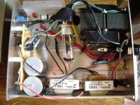
Here are some pics.
Hi all.
I just got my version of Richard Murdey's 6DJ8 phonostage
up and running, and it sounds just fine.
http://www.geocities.com/rjm003.geo/rjmaudio/diy_pho3.html
I don't hear any real difference beetween it and my Hafler DH110
which by what I have read has an excellent phono section.
My turntable is nothing very special however.
Here are some pics.
Looks great.
I need to do a phonostage soon (am using a crappy SS phonostage) and I was looking at the hagtech's cornet octal (6sl7 and 6sn7) and this phonostage (6dj8) but since I have tons of 6n1p, I might do a 6n1p phonostage with slight modification of the circuit.
Great job on your 6dj8 phonostage.")
I need to do a phonostage soon (am using a crappy SS phonostage) and I was looking at the hagtech's cornet octal (6sl7 and 6sn7) and this phonostage (6dj8) but since I have tons of 6n1p, I might do a 6n1p phonostage with slight modification of the circuit.
Great job on your 6dj8 phonostage.
Hi.
Richard Murdy's page on this amp says 38db. Should be about
90x. 30x per stage with a 10 (20db) loss in the passive filter.
I am using a Hafler 110 preamp. the volume settings are about
the same as when using the built in phono section. The sound
is just as good too. The Hafler phono has a very good reputation.
So I didn't really need the tube phono but it was a fun project.
Watch out for hum. I just left the heaters floating and got alot of
hum. I have grounded one side of the heaters at the outboard
psu and the hum has dropped alot. I am going to ground them
in the amp instead and see how that works. I don't really want
to reference heater supply to a positive voltage because the
rectifier diode heater uses the same supply.
Since taking theese pictures I have fiished the lid for the psu.
Now I need to finish the case for the phonostage.
Rolf.
Are you using an IDH rectifier? If so then, I think, referencing the heater at a higher voltage (within reason) should not be a problem and I would think that it would make a world of difference. Tightly twisted heater wires is of course recommended as well. I did this on a high gain guitar amp and there was absolutely no audible hum.
just a newbie's opinion.
just a newbie's opinion.
I gather that your heater supply does not have a center tap for ground. I don't think you need to reference the heater to a positive supply, the cathode voltage is very, very low.
If you don't have a center tap heater supply, try connecting each leg of the heater supply to ground with 100 ohm resistor. This seems to work for me.
I started drilling my chassis for this preamp, but I will be using 6n1p because I have tons of them. Thanks.
If you don't have a center tap heater supply, try connecting each leg of the heater supply to ground with 100 ohm resistor. This seems to work for me.
I started drilling my chassis for this preamp, but I will be using 6n1p because I have tons of them. Thanks.
Hi Mike.
Yes it is an indirectly heated diode a 6x4. I would't think it would be possible to share heater supply with the amp triodes otherwise.
Thank's for sending those plugs. I did go with a different
connector however.
alexg,
I think I will try you idea. good luck with your build!
ps. I did twist the heater wires.
Hi Dawooffer.
I am using Hafler DH110 preamp and homemade 6EM7 series
single ended power amp. Phonostage sill hums a bit too
even after using alexg's idea. I don't hear the hum when
playing a record, only with volume up fairly loud.
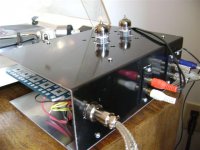
here are some more pictures.
I am using Hafler DH110 preamp and homemade 6EM7 series
single ended power amp. Phonostage sill hums a bit too
even after using alexg's idea. I don't hear the hum when
playing a record, only with volume up fairly loud.
here are some more pictures.
Attachments
Well,
What I did was put a large solid copper wire from a mains
wiring cable, the type that is used inside walls, around the
tube sockets in a U shape. The negative from the power supply
I attached to the bottom of the U. Then I made all my ground
connections to this ground buss. An earth ground wire was
brought from the power supply to the amps case. the only
connection beetween the negative supply rail and earth ground
is at the input jacks.
I don't know if it is the best way but I figured since it worked
in my poweramps quite nicely, I would try it in this project too.
Another thing I have noticed, when volume is turned way up
with no record on, the wooffers were making large excursions
at a very low frequency, maybe 4 cps. I figured why not try
a little negative feedback? Rather unscientificaly, I put 30m ohms
between the output and the cathodes of the input stage. when I plugged it back in,
one channel had very low output. after a little messing around I
found I used the wrong resistors here, 600 ohms.
After fixing this, I think the woofers are not flailing about quite
so much. It may just be my imagination but the bass might be
a little tighter as well.
Anyone think I should take it furthe to 15 megs?
And here I thought I could never afford a motorboat!
But seriously, a breif search seems to sugest that lclc filters
are prone to this problem. I based my filter on Richard Murdey's
design as shown here. Rectifier is hybrid bridge with 6x4 tube.
filter components I ended up with are:
15H(1026 DCR), 22uf, 7H(340 DCR), 20uf.
The chokes are what I could find that were close to Richards
original plan. Maybe the first choke needs to be several times
the inductance of the second? I will need to do some research.
Attachments
If you are philosophically opposed to active regulation, C7 and C8 on the RLM schematic could easily be made much larger, 100u or more. That could help.
I haven't modeled your raw supply in PSUD2, but you may want to, and pay particular attention to the effect of a current step on the raw supply response.
I haven't modeled your raw supply in PSUD2, but you may want to, and pay particular attention to the effect of a current step on the raw supply response.
Thank's guy's
I played with PSU2. It seems a much bigger output capacitor
could be the answer.
Sy. Not opposed to active reglation. It might come to that yet.
I have never played with regulation yet. Changing those
decoupling capacitors in the phono circuit, not really an option.
I would likely make a big mess of that circuit board. It would be
much easier to do had I used point to point. Oh well.
Rolf.
- Status
- This old topic is closed. If you want to reopen this topic, contact a moderator using the "Report Post" button.
- Home
- Amplifiers
- Tubes / Valves
- Phono stage success!