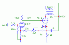
I got inspired by Darius's musings on Loftin White amps, so I modified my 801 resistor loaded amp into a Loftin-White amp, but using a triode for the input tube, as I don't need the high sensitivity of the original.
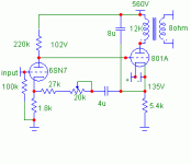
The power supply noise nulls out with the pot set at 10k (37k total), which is very close to the predicted value. The resistor chain divided by u (37k/20) should equal the resistance of the input cathode resistor (18k). Seems very quiet. I get about 0.9W output at 2.6vRMS input. Frequency response on the low end is about 100Hz before the transformer saturates. The -3db point on the upper end is 41kHz. Square waves look good. Good enough to go ahead and build it out. I won't use it full range, so I wound the transformer for the top end. I'll probably go with something like 12-14k for the final pair of OPT's.
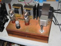
Amp
The power supply noise nulls out with the pot set at 10k (37k total), which is very close to the predicted value. The resistor chain divided by u (37k/20) should equal the resistance of the input cathode resistor (18k). Seems very quiet. I get about 0.9W output at 2.6vRMS input. Frequency response on the low end is about 100Hz before the transformer saturates. The -3db point on the upper end is 41kHz. Square waves look good. Good enough to go ahead and build it out. I won't use it full range, so I wound the transformer for the top end. I'll probably go with something like 12-14k for the final pair of OPT's.
Amp
Attachments
Hello Sheldon,
congratulations for making worlds first 801 Loftin White amp
and sharing it with us here in the forum.
Clever to use an indirectly heated rectifier tube to
get a soft start for the 801.
Don't forget this cap: post 13
I recommend to make the 6SN7 AC heater voltage symmetrical.
(Two resistors to 26VDC rail.)
Kind regards,
Darius
Sheldon said:The power supply noise nulls out with the pot set at 10k (37k total), which is very close to the predicted value. The resistor chain divided by u (37k/20) should equal the resistance of the input cathode resistor (18k).
Sheldon,
The schematic shows a 6SL7, which has a u=70, not 20, and the cathode resistor is 1.8k not 18 like in your description. Something does not jive in your calculations.
-- josé k.
Re: Re: loftin white 801 amp
My German is not too good, but I interpreted your comments to suggest that it might not be technically required. I figured to try it without first, then try it with the extra cap, after I had a chance to wire thing up neatly and listen in stereo. Have to wind up a couple of cores first.
I have that, just not shown on the schematic that I quickly threw together. My haste explains the errors noted by Jose. It is SN7 and the resistor is 1.8k. I'll correct the schematic.
Sheldon
oldeurope said:
My German is not too good, but I interpreted your comments to suggest that it might not be technically required. I figured to try it without first, then try it with the extra cap, after I had a chance to wire thing up neatly and listen in stereo. Have to wind up a couple of cores first.
oldeurope said:I recommend to make the 6SN7 AC heater voltage symmetrical.
(Two resistors to 26VDC rail.)
I have that, just not shown on the schematic that I quickly threw together. My haste explains the errors noted by Jose. It is SN7 and the resistor is 1.8k. I'll correct the schematic.
korneluk said:The schematic shows a 6SL7, which has a u=70, not 20, and the cathode resistor is 1.8k not 18 like in your description.
Sheldon
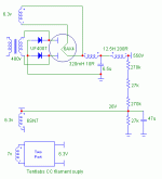
Here's what it actually looks like now, with errors fixed. One channel with transformer, one channel just wired to bias up the tubes. I did this to load the power transformer so I could check voltages with the stereo load.
Not noted on the schema is that each 801 has it's own filament supply.
Sheldon
Not noted on the schema is that each 801 has it's own filament supply.
Sheldon
Attachments
Full Build
Finished up a second transformer and did some testing. The final cap to ground after the PS choke, as suggested by Darius, does make a significant difference in residual hum. Without the cap, I hear hum (maybe 3mV or so), with the cap it's less than 0.5mV. Not shown on the schematic are fuses in the B+ line, in case of input tube failure.
Clip occurs at 2.6V in and, coincidentaly, 2.6V output, which calculates to about 850 blazing milliwatts of power.
The -3dB point for one transformer is 65kHz, and the other is 45kHz, which suggests that my winding technique needs a little work. Saturation at full power starts to show up at 100Hz.
At about 1V input (Im guessing here, as that is with full output on the soundcard) I see the 2nd at -60dB, 3rd at -70db, and some 4th and 5th below 100dB.
Here's the updated schematic.
Attachments
under the hood
This amp looks quite simple, and it does have a low part count. In return for the low part count, it has to be well planned. In an amp made with discreet stages, especially AC coupled, you have lots of freedom to change one stage without changing the other. Not so here, as all the operating parameters work together and have to be spec'd with that in mind. I'm not going to say that there are no caps in the signal path, but the influence of the caps on the signal is very largely neutralized in this design. And the caps don't need to be big, so you can use all film caps. Those two guys were pretty clever, as Darius has noted.
This amp looks quite simple, and it does have a low part count. In return for the low part count, it has to be well planned. In an amp made with discreet stages, especially AC coupled, you have lots of freedom to change one stage without changing the other. Not so here, as all the operating parameters work together and have to be spec'd with that in mind. I'm not going to say that there are no caps in the signal path, but the influence of the caps on the signal is very largely neutralized in this design. And the caps don't need to be big, so you can use all film caps. Those two guys were pretty clever, as Darius has noted.
Attachments
Looks good, how do they sound so far?... Are they Mid-HF amps in a multi-amp system? Did you use LF BW limited OPTs?
What type of Russian caps did you use (wax/paper?) with what VDC rating? I hope there are 47uF in not so large physical dims.
BTW, if you're looking for transformer covers vt4c.com has some. Although I'm not sure if they have the right size for your self-wound OPT's.
A DHT driver would be nice. But of course, most of the passive parts values would need to be changed/re-adjusted. And it would need stiff filament supplies for them like Tentlabs modules or diy etc.
fred76 said:Looks good, how do they sound so far?... Are they Mid-HF amps in a multi-amp system? Did you use LF BW limited OPTs?
What type of Russian caps did you use (wax/paper?) with what VDC rating? I hope there are 47uF in not so large physical dims.
BTW, if you're looking for transformer covers vt4c.com has some. Although I'm not sure if they have the right size for your self-wound OPT's.
A DHT driver would be nice. But of course, most of the passive parts values would need to be changed/re-adjusted. And it would need stiff filament supplies for them like Tentlabs modules or diy etc.
Yes, mid-hf. I didn't limit the LF so much as just not worry about it, and instead optimize for the high frequencies.
Those are Russian paper caps, with 400vAC rating. I've used them up to 625VDC with no failures. No need for large caps with this design. The amp is quiet as a grave with the values shown. You can put your head in the horn with the TAD 2001 and hear nothing but maybe, maybe a very faint hint of hum.
If you want a two stage amp, you'd have to have a DHT with mu of 20 or so to get adequate sensitivity. If you have a preamp with gain, you might get away with less. Could try something like 3A5 (mu of 15), with battery powered filaments, as it requires only 1.2V. I might try it some day.
Sheldon
Re: Full Build
Here's an interesting little tidbit: I didn't pot the bobbins, but applied shellac to the windings as I proceeded. And I wound each and finished it up in the same day, so the shellac was not completely dry. The first transformer had been sitting a few days before testing, the second was tested the day after it was made. Now a month later, both transformers give the same -3dB point of around 65k. I was surprised to find that a few day difference in curing made a significant difference. Not surprisingly, the 10k square waves look very similar too now (and good, just a little ringing visible as a slight ripple on the top and bottom).
Sheldon
Sheldon said:The -3dB point for one transformer is 65kHz, and the other is 45kHz, which suggests that my winding technique needs a little work. Saturation at full power starts to show up at 100Hz.
Here's an interesting little tidbit: I didn't pot the bobbins, but applied shellac to the windings as I proceeded. And I wound each and finished it up in the same day, so the shellac was not completely dry. The first transformer had been sitting a few days before testing, the second was tested the day after it was made. Now a month later, both transformers give the same -3dB point of around 65k. I was surprised to find that a few day difference in curing made a significant difference. Not surprisingly, the 10k square waves look very similar too now (and good, just a little ringing visible as a slight ripple on the top and bottom).
Sheldon
Re: Full Build
Sheldon,
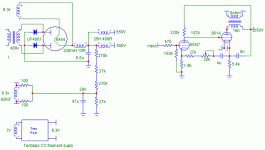
In your schematic, where is the 1uF cap from the ground input to the cathode resistor of the input tube as shown on the original schematic? Is it necessary?
Sheldon,
In your schematic, where is the 1uF cap from the ground input to the cathode resistor of the input tube as shown on the original schematic? Is it necessary?
An externally hosted image should be here but it was not working when we last tested it.
Sheldon said:I redrew the schematic. Should be easier to see the equivalent parts.
Sheldon
I do not see the 1uF cap at the input and the 6SN7 grid leak resistor goes straight to ground.
Where do you connect the ground from the input jack? In the original LW circuit, it goes to the cathode resistor of the output tube.
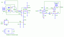
here is a clearer picture:
An externally hosted image should be here but it was not working when we last tested it.
korneluk said:I do not see the 1uF cap at the input and the 6SN7 grid leak resistor goes straight to ground.
Where do you connect the ground from the input jack? In the original LW circuit, it goes to the cathode resistor of the output tube.
In the original, the input common is taken from the cathode resistor string, to bias the tube and make all the DC voltage relationships work out. But any noise (current variation) at that point will be added to the input signal. The cap is there so that the cathode and input common can both float on the cathode of the output tube. When the bias is adjusted, the noise on input common, relative to the main ground, will vary in amplitude, so the reference is taken at the input cathode, which is already compensated and constant in level.
In the triode versions shown, the input common is not influenced by current in the output cathode resistor, so the cap is not needed.
Sheldon
- Status
- This old topic is closed. If you want to reopen this topic, contact a moderator using the "Report Post" button.
- Home
- Amplifiers
- Tubes / Valves
- loftin white 801 amp