oshifis said:If you put the grid resistor before R1, it will be parallel with R7
True. But this will lose you gain for no reason. Is it worth it just to simplify the calcs a bit?
Edit: i may be wrong about this; gotta go to gym now, will look into it later
Thank you Carsten!
This clears things up considerably and shows that oshifis was dead on when writing that the caps are to high by a factor 10!
Looks like "somebody" made a conversion error from uF to nF....
This also shows me how to increase the gain, grat!
If I may ask, do you have the mentioned part-list as well?
Can you say what input voltages (before plate resistor) we are talking about?
regards
Dieter
I actually remembered the 715k from Daniel but was lazy to look for my Audio Amateur stack. Built it soon after the article came up and didn't like it much, but no doubt the riaa is correct. Apart from the cap values it also has 10M instead of 2.2M (parallel is 667k). Whoever built your pre was quite clueless.
Btw, there are two sets of values for the cascode resistors, so changing the 390R to 100R increases the gain substantially.
Btw, there are two sets of values for the cascode resistors, so changing the 390R to 100R increases the gain substantially.
Do you know of any better design using two 6DJ8 or point me in the right direction.
I have a lot of old CCAs from Siemens (1962) and would like to use a proven high quality circuit for my phono-amplification.
Another amateur question: I made some Simulation with B2 Spice (downloaded yesterday evening) and these values seem to be better suited (attachment). Am I wrong, respectively can I apply them to this circuit or is the one form Audio Amateur just fine?
Attachments
75k makes it more dificult to ignore the output impedance of the cascode. To get an exact value is not that simple and the best route is to actually measure the particular tubes at the operating point. In any case practical values are usually a compromise as getting precise values with a good sounding dielectic is not trivial.
dikarner said:Do you know of any better design using two 6DJ8 or point me in the right direction.
http://vacuumstate.com/various/SP-15_Article.pdf
Hi all,
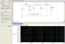
I just wanted to report back the final results. The picture shows the circuit as it is now. Don't get fooled by the curve, the variance is within 0.3db
Now it sounds as it should be, even the gain is sufficient.
Thanks for all your help, I learned a LOT!
BR
Dieter
I just wanted to report back the final results. The picture shows the circuit as it is now. Don't get fooled by the curve, the variance is within 0.3db
Now it sounds as it should be, even the gain is sufficient.
Thanks for all your help, I learned a LOT!
BR
Dieter
Attachments
it seems to work, yes. I did not know this limitation.
What are the potential downfalls with to high a grid resistior?
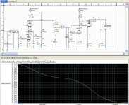
according to the simulation with B2 Spice: In combination with the other compnents as shown, lower grid resistor values significantly increase the loss at low frequencies: starting at 300Hz going down to -2.8db at 20Hz with 1meg.
I will run different numbers and see if I can come up with different result
Intrigued by your proposition to move the coupling capacitor and the grid resistor before the EQ Network I played with the positions and this one position had the flattest curve as a result.
Unfortunately I do not own measuring equipment So I cannot actually confirm the simulation results with hard evidence.
What are the potential downfalls with to high a grid resistior?
according to the simulation with B2 Spice: In combination with the other compnents as shown, lower grid resistor values significantly increase the loss at low frequencies: starting at 300Hz going down to -2.8db at 20Hz with 1meg.
I will run different numbers and see if I can come up with different result
Intrigued by your proposition to move the coupling capacitor and the grid resistor before the EQ Network I played with the positions and this one position had the flattest curve as a result.
Unfortunately I do not own measuring equipment So I cannot actually confirm the simulation results with hard evidence.
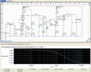
it does not get better then 0.25db with higher C4 values. It would get better with other values in the RIAA Network, but this is what I have at hand and 0.25 is pretty good for the start.
I will try it in the weekend and report back if it improves the sound.
please answer this question: What are the downfalls with using a grid resistor much higher then what the datasheet allows?
I will try it in the weekend and report back if it improves the sound.
please answer this question: What are the downfalls with using a grid resistor much higher then what the datasheet allows?
#36
Hello dikarner,
what about the influence of the stylus, pic up system, load capacitance of the calble, load resistance ... speaker in the curve?")
DC voltage drop that changes bias.
Kind regards,
Darius
Originally #36 posted by dikarner
it does not get better then 0.25db ...
Hello dikarner,
what about the influence of the stylus, pic up system, load capacitance of the calble, load resistance ... speaker in the curve?
Originally #36 posted by dikarner
...
What are the downfalls with using a grid resistor much higher then what the datasheet allows?
DC voltage drop that changes bias.
Kind regards,
Darius
dikarner said:please answer this question: What are the downfalls with using a grid resistor much higher then what the datasheet allows?
Some ECC88 won't bias correctly
Ah so, the bottom curve is the deviation from the ideal. Then it is in order and it should also sound good. Tell us how does it perform.dikarner said:it does not get better then 0.25db with higher C4 values. It would get better with other values in the RIAA Network, but this is what I have at hand and 0.25 is pretty good for the start.
I will try it in the weekend and report back if it improves the sound.
Over the weekend, I played around quite much with the phonostage. First I moved coupling-cap and grid resistor as described above infront ofthe RIAA network and changed the value to 1meg.
This did not change anything in sound quality. The tube seemed to have biased alright before. What I did not like, was the tonality. It sounded a little bit thin. I tweaked and improved marginally by reducing the value of R9 from 88.3K to 86.7K. This took some edge out of the voices but hardly.
Then I increased the value of the coupling caps, which helped again a little.
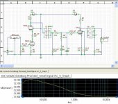
Then I replaced some resistors from carbon or metal-film to carbon-mass (don't know the correct english term: http://www.steinmusic.de/audiofino/bauteile-widerstaende.html ). This helped much more than the previous 2 approaches, but I still was not satisfied. The relevant resistor which I had at home are marked ind dht diagram with "_KP" behind the number.
Then I tried a different approach: Inspired by the line-stage, which uses a 7721/7722 pentode in triode mode I replaced the second 6922, with a 7721 in triode mode.
That was it. Then I was very happy with the sound and this is how I will leave it for now.
What the picture does not show: Grid 2 is directly connected to the plate.
This did not change anything in sound quality. The tube seemed to have biased alright before. What I did not like, was the tonality. It sounded a little bit thin. I tweaked and improved marginally by reducing the value of R9 from 88.3K to 86.7K. This took some edge out of the voices but hardly.
Then I increased the value of the coupling caps, which helped again a little.
Then I replaced some resistors from carbon or metal-film to carbon-mass (don't know the correct english term: http://www.steinmusic.de/audiofino/bauteile-widerstaende.html ). This helped much more than the previous 2 approaches, but I still was not satisfied. The relevant resistor which I had at home are marked ind dht diagram with "_KP" behind the number.
Then I tried a different approach: Inspired by the line-stage, which uses a 7721/7722 pentode in triode mode I replaced the second 6922, with a 7721 in triode mode.
That was it. Then I was very happy with the sound and this is how I will leave it for now.
What the picture does not show: Grid 2 is directly connected to the plate.
Attachments
- Status
- This old topic is closed. If you want to reopen this topic, contact a moderator using the "Report Post" button.
- Home
- Amplifiers
- Tubes / Valves
- Tube phono amp repair/redesign help wanted