Hello,
I'm thinking of building this phono preamp, Bob's Vacuum Tube Phono Preamp. But, as I'm new to this, I have no idea what the power supply would look like, does anyone have any ideas?
Thank you very much,
Steven Paul
I'm thinking of building this phono preamp, Bob's Vacuum Tube Phono Preamp. But, as I'm new to this, I have no idea what the power supply would look like, does anyone have any ideas?
Thank you very much,
Steven Paul
Granted a regulated supply would probably deliver the best performance but I'm wondering if you could get away with just a
150 volt and 90 volt regulator in series. You would end up with somewhere around 240-255 volts which should be close enough.
I am wondering why there isn't a plate resistor for the second half of the 12SN7.
150 volt and 90 volt regulator in series. You would end up with somewhere around 240-255 volts which should be close enough.
I am wondering why there isn't a plate resistor for the second half of the 12SN7.
Steven,
You have 2 power supply issues. Along with the 250 V. B+ rail, you also need 450 mA. of 12 VDC for the heaters in each channel.
Rectify the O/P of a R/S catalog # 273-1512 trafo using a MBR20100CT common cathode twin Schottky diode. Filter with 25 WVDC/15000 μF. 'lytic. Individual 7812 3 terminal regulators feed the heaters of each channel.
Individual TO92 case LR8 3 terminal adjustable regulators will take care of the 250 V. B+ for the 12SL7s, but you need something more substantial for the 12SN7s. A choke I/P filtered B+ rail would be OK for that job. One way or another, the 12SL7s need to be decoupled from the 12SN7s.
If you have yet to buy tubes, consider the Locktal based 14F7 and 14N7 as corresponding replacements for the 12SL7 and 12SN7. Locktal based tubes, particularly those with "12" V. heaters, are inexpensive.
I am wondering why there isn't a plate resistor for the second half of the 12SN7.
The 2nd 1/2 of the 'SN7 is a cathode follower that buffers the preamp's O/P.

Eli
Thanks for pointing that out I took a quick look and it didn't dawn on me.
Are you putting the heaters in series for each channel?
Why is the LR8 necessary? Wouldn't a 90 and 150 gas regulator tube in series be ok? Or would that work ok for the 12SN7 ?
Wouldn't a CCS in place of the cathode resistor (R2) and possibly another one in place of (R7) help performance?
Thanks for pointing that out
I took a quick look and it didn't dawn on me.Are you putting the heaters in series for each channel?
Why is the LR8 necessary? Wouldn't a 90 and 150 gas regulator tube in series be ok? Or would that work ok for the 12SN7 ?
Wouldn't a CCS in place of the cathode resistor (R2) and possibly another one in place of (R7) help performance?
burnedfingers said:Is the long tail pair (12SL7) configured correctly?
Long tail pair? Are we looking at the same circuit?
Why is the LR8 necessary? Wouldn't a 90 and 150 gas regulator tube in series be ok? Or would that work ok for the 12SN7 ?
Stacked gas discharge VR tubes should be just fine, as the minimum current draw requirements could be met by using a bleeder resistor. However, the "sand" parts are inexpensive and occupy way less space. If recyclable stuff is available in the "junk box", use it. I'd go with LR8s, when buying all new parts.
Will this work?
If you use Schottky diodes in the heater PSU bridge, you should be OK. I'm afraid of dropouts, when using 7812s, if PN junction diodes are used in the bridge. Here, the difference in forward drop of approx. 1 V. matters.
Use separate regulator stacks for the 12SL7s and 12SN7s. I see no decoupling networks in the schematic linked. I think a pair of 12SL7s will draw enough current to forego a bleeder resistor in that "leg".
If you use Schottky diodes in the heater PSU bridge, you should be OK. I'm afraid of dropouts, when using 7812s, if PN junction diodes are used in the bridge. Here, the difference in forward drop of approx. 1 V. matters.
Isn't the transformer you specified Radio Shack 273-1512 a 25.2 volt transformer? If so isn't there enough voltage after rectification and filter so that you wouldn't have to worry about the extra forward drop?
Yes, a horrible way to draw a circuit. All these are of course grounds. Seems like the designer never bothered to update the circuit in 13 years. Not a good sign.
Why don't you look for another design? The topology is sound and generally similar to Arthur Loesh's split riaa circuit. I'd rather go for the original, or the Oz variant or one of Allen Wright's designs.
Why don't you look for another design? The topology is sound and generally similar to Arthur Loesh's split riaa circuit. I'd rather go for the original, or the Oz variant or one of Allen Wright's designs.
Why don't you look for another design?
I would assume that HawkSpeed is interested in this particular design and that is why the thread. I also am interested in this design because of the tubes it uses and the nostalgia.
Analog_sa why not comment with something that could be considered useful instead of point out my mistakes or the lack of update in the last 13 years. As smart as you must be why not use that tallent to help update the schematic or to correct the RIAA compensation that surely must be in need of some help.
Mapletree audio I am told markets a design that is somewhat similar to this one except it uses a different input tube that has a common cathode. I have personally listened to this phono preamp and found it to be quite pleasing and very neutral and uncolored.
Why not take the time to contribute something useful and update this somewhat simplistic animal and make this thread one that can be considered as a learning tool and a inspiration?
I like the apparent simplicity of this design, but this is my first project so there are questions to ask...
Thanks for the clarification about the diagram, it's starting to make sense now.
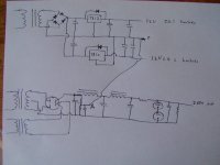
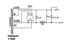
On that note, how about this for a power supply? But I'm not sure what you mean by decoupling Eli, sorry.
And as it seems most power transformers have a 5v and 6.3v filament I'm still not sure how to get the 12v I'd need for my heaters. I've tried Googling, but so far to no success.
Thanks for the clarification about the diagram, it's starting to make sense now.
On that note, how about this for a power supply? But I'm not sure what you mean by decoupling Eli, sorry.
And as it seems most power transformers have a 5v and 6.3v filament I'm still not sure how to get the 12v I'd need for my heaters. I've tried Googling, but so far to no success.
Attachments
I'm still not sure how to get the 12v I'd need for my heaters.
Purchase the Radio Shack PN 273-1512 and use the suggestion from Eli
Rectify the O/P of a R/S catalog # 273-1512 trafo using a MBR20100CT common cathode twin Schottky diode. Filter with 25 WVDC/15000 ìF. 'lytic. Individual 7812 3 terminal regulators feed the heaters of each channel.
It would appear that you will need to build up two of these to take care of the heaters.
You can then build up the power supply based on Eli's suggestion or one of your choice. I'm going to use the gas regulator tubes since I have a mega supply of them and I also like the cool look of them.
Hopefully HawkSpeed we will be able to get some more good ideas and learn in the process. I am going to make this phono preamp also because of hearing a similar circuit and the fact that I have the tubes. Maybe SY will join in and give some good advice and ideas. This is a worthwhile project Hawkspeed so don't let it get you down as it is well within your grasp.
It's not a trivial problem. The circuit itself doesn't have very good power supplky rejection, so the power supply has to be very quiet. If it were my own unit, I'd probably use separate B+ and heater transformers, no toroids, decent-but-not-exotic rectifiers like UF4007, and a C input filter with a relatively small input C (like 47-100u), a moderate output C, then pre-regulate with a Maida regulator to perhaps 20 more volts than I need. Then use an RCRC to feed each supply point.
A perfectly reasonable and maybe even superior approach is the shunt regs that Allen Wright published. That has the advantage of boards and complete documentation, not to mention extensive field use.
A perfectly reasonable and maybe even superior approach is the shunt regs that Allen Wright published. That has the advantage of boards and complete documentation, not to mention extensive field use.
Isn't the transformer you specified Radio Shack 273-1512 a 25.2 volt transformer?
Yes, the 273-1512 is 12.6-0-12.6 and the diodes in the common cathode connection MRBR20100CT are rated for 100 PIV/10 A. You set up a "classic" full wave CT PSU.
Look at the data for the 273-152. It's rated for 2 A. When a large cap. I/P filter is employed, plan on accessing only 1/2 of the winding's capability. Still, that's 1 A. at 25.2 VAC. So, up to 2 A. of 12 VDC should be available. Use a 7812 in each channel. A draw of 450 mA. will not overtax the IC, as long as it's properly heatsinked.
The performance of the 7812 can be improved significantly by placing a Panasonic "V" series cap. directly across its I/P. Place a 10 μF. 'lytic directly across the regulator's O/P. Place a 4.7 μF. 'lytic bypassed by a 10 nF. ceramic part across the heater pin connections of each octal socket.
- Status
- This old topic is closed. If you want to reopen this topic, contact a moderator using the "Report Post" button.
- Home
- Amplifiers
- Tubes / Valves
- Power supply for 12SL7 phono preamp