Hello,
I am searching for a unity µ triode as a phase inverter.
Something like the triode section of the ECLL800.
At the moment I am using a 6080 (µ ≈ 1,5 @ 1mA)
but it is a bit oversized in this application.
Any other suggestions?
thanks,
Darius
I am searching for a unity µ triode as a phase inverter.
Something like the triode section of the ECLL800.
At the moment I am using a 6080 (µ ≈ 1,5 @ 1mA)
but it is a bit oversized in this application.
Any other suggestions?
thanks,
Darius
oldeurope said:Hello,
I am searching for a unity µ triode as a phase inverter.
Something like the triode section of the ECLL800.
At the moment I am using a 6080 (µ ≈ 1,5 @ 1mA)
but it is a bit oversized in this application.
Any other suggestions?
thanks,
Darius
You dont need a unity u valve for a phase splitter.
Just set the anode resistor and cathod resistors to the same value. Same current through both means same voltage but 180 degrees out of phase.
#2 no fb ...
Hello,
I am searching a unity µ triode as a phase inverter.
Something like the triode section of the ECLL800.
No negative feedback please.
Sorry I forgot to point this out.
Kind regards,
Darius
nigelwright7557 said:
You dont need a unity u valve for a phase splitter.
Hello,
I am searching a unity µ triode as a phase inverter.
Something like the triode section of the ECLL800.
nigelwright7557 said:
Just set the anode resistor and cathod resistors to the same value.
No negative feedback please.
Sorry I forgot to point this out.
Kind regards,
Darius
Re: #2 no fb ...
But there is no feedback in my example !
oldeurope said:
Hello,
I am searching a unity µ triode as a phase inverter.
Something like the triode section of the ECLL800.
No negative feedback please.
Sorry I forgot to point this out.
Kind regards,
Darius
But there is no feedback in my example !
No negative feedback please.
So, Darius, what sort of splitter had you in mind?
#2 #4 #5
@#2 #4 current feedback.
@#5
Hello ray_moth,
I am searching for a unity µ triode as a phase inverter.
Something like the triode section of the ECLL800.
See attachment below.
Kind regards,
Darius
@#2 #4 current feedback.
@#5
ray_moth said:
So, Darius, what sort of splitter had you in mind?
Hello ray_moth,
I am searching for a unity µ triode as a phase inverter.
Something like the triode section of the ECLL800.
See attachment below.
Kind regards,
Darius
Attachments
I don't think one will find a Mu = 1 tube since that would require the plate to be as close to the cathode as the grid, or a very open mesh grid, which would be non-linear. Since the Mu factor is a measure of internal feedback anyway, why the avoidance of feedback techniques?
If one "must" get a low Mu, try the voltage mirror scheme used at the input of the Aikido amps. Use of an identical triode as the active load drops the Mu in half by halving Rp. Using more than one active load triode in parallel will get you even lower Mu.
Another approach is to put thermionic diodes in series with the cathode path. This will lower Mu asymtotically toward unity, but will raise output Z.
Another way would be something like the 6ME8 beam deflector tube, with the plate load resistors adjusted to a value that gives unity gain. The voltage swing on the plates will then be exactly countering the effect of the deflection voltage on the deflectors.
Don
Well, there is always inverted triode. Mu'=1/Mu
Drive the plate negative and take a Mu' output
from forward conduction of the the grid.
Mu*(1/Mu)=1
I dunno how suitable is 6922. Just pulled that
from the air cause it can tolerate the cathodes
being at wildly different voltage. Perhaps 6N30Pi
might have a beefier grid? 6080 is good for invert,
but you wanted something smaller.
Incomplete OT schematic without part values
just the way you like em... I'm sure you could
even find some way to turn this Loftin/White...
I'm not sure which rail you prefer common to
power noise in this situation. Depends what
are you intending to drive in the next stage?
What was the trouble with Mu>1 and a resistive
divider??
---------------------------------------------------------
Nutz... I inverted twice.... Thats not helpful!
If I make the inverted triode behave as a follower
then overall Mu does not revert to 1 as intended.
I don't see an easy way to fix this.
Attachments
Umm.... Ken,
Two inversions = piece of wire. Nice try though!
Maybe ground the grid of the output 1/Mu tube and take the output signal off the cathode. (probably get 1/(Mu-1) for inverted tube , so will end up with -Mu/(Mu-1) overall gain.
(Guess we posted at the same time)
Don
Two inversions = piece of wire. Nice try though!
Maybe ground the grid of the output 1/Mu tube and take the output signal off the cathode. (probably get 1/(Mu-1) for inverted tube , so will end up with -Mu/(Mu-1) overall gain.
(Guess we posted at the same time)
Don
searching for a unity µ triode ...
Hello Don, hello forum
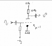
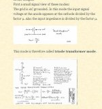
whow you mean the "triode transformer mode".
 This isn't an "inverted" triode. I the "inverted mode" µ'<1/µ. See graph.
I am searching for a unity µ triode as a phase inverter.
Something like the triode section of the ECLL800 because
it is an inverter as simple as can be. It provides excellent
power supply riple rejection, low output impedance, no
negative feedback, very low input capacitance, excellent linearity and
a high well known factor.
I'll leave the 6080 in place, it takes much filament power
but it does this job very well.
Thanks for the replies,
Darius
Originally #11 posted by smoking-amp
... Maybe ground the grid of the output 1/Mu tube and take the output signal off the cathode. (probably get 1/(Mu-1) for inverted tube , so will end up with -Mu/(Mu-1) overall gain.
...
Don
Hello Don, hello forum
whow
you mean the "triode transformer mode". This isn't an "inverted" triode. I the "inverted mode" µ'<1/µ. See graph.I am searching for a unity µ triode as a phase inverter.
Something like the triode section of the ECLL800 because
it is an inverter as simple as can be. It provides excellent
power supply riple rejection, low output impedance, no
negative feedback, very low input capacitance, excellent linearity and
a high well known factor.
I'll leave the 6080 in place, it takes much filament power
but it does this job very well.
Thanks for the replies,
Darius
Attachments
"You mean like this?"
Yup!
"This isn't an "inverted" triode."
Oh. I see Steve Bench uses opposite DC voltages for his inverted triode. But the AC operation is nearly the same either way. I think Frederick Terman came up with the scheme using reversed DC voltages a long way back: (Electronic and Radio Engineering, 4th edition, page 209 or "The Inverted Vacuum Tube ..." Proc. IRE vol 16, p 447, April 1928)
As Ken has it drawn now, I think the second tube gives 1/(Mu-1) voltage gain at it's cathode output if loaded by a CCS instead of a cathode resistor. But reduced gain with a resistor load of course.
Unfortunately, the first tube won't be getting near its ideal Mu voltage gain though with the low input impedance of the 2nd tube's plate loading it down.
Using a pentode (for V2) with screen grid input and cathode output (grounded grid1) would give higher input impedance. (plate at B+)
Going even further out on a limb, how about running the screen grid at some negative voltage to get very high input impedance there, with the plate at B+, and a CCS pulling down (negative) on the cathode output. (Grid1 grounded. The CCS would pull the cathode down enough to make the grid1 to cathode positive enough to cancel out the negative screen grid bias) Now it looks like a REAL 1/(Mu-1) triode.
Now lets see. Get rid of the 1st inverting Mu gain tube and use a pentode for the sole gain stage. Input at the negative screen grid with output at the plate (pulled positive to B+ by load resistor). CCS pulling down (negative) on the cathode with grid 1 grounded. Adjust plate load resistor for unity gain.
Darn...., puts out constant current on the plate. Maybe use a cathode resistor instead of CCS.
Don
smoking-amp said:Going even further out on a limb, how about running the screen grid at some negative voltage to get very high input impedance there, with the plate at B+, and a CCS pulling down (negative) on the cathode output. (Grid1 grounded. The CCS would pull the cathode down enough to make the grid1 to cathode positive enough to cancel out the negative screen grid bias) Now it looks like a REAL 1/(Mu-1) triode.
I now wonder how a 1/(Mu-1) triode would perform with Mu=1

"I now wonder how a 1/(Mu-1) triode would perform with Mu=1"
Oops.... Looks like all those 1/(Mu-1) 's above should be 1/(Mu+1) I was adding the cathode voltage shift effects into the plate to cathode voltage with the wrong polarity.
Tube Mu = 1 example:
Lets say the plate shifts positive by 2 delta (with respect to ground) and the cathode shifts positve (with respect to ground) by one delta. Then the final plate to cathode shift is 1 delta and the grounded grid to cathode shift is -1 delta. So internal to the tube (referenced to the cathode), the Mu of 1 (-1 actually since it is inverting internally) is observed, but externally (referenced to ground) Mu of +1/2 results (+2 delta in on plate for +1 delta out on cathode).
Don
Well, the way I figured, as long as the voltage difference between
input and cathode(triode1) was matched by an inverse inbetween
output and grid(triode2)... And both share the same plate voltage.
Both triodes would conduct the same. Any AC at the plates would
represent only the power supply ripple...
As input differs from inverse at the output, we begin to see a very
large voltage swing at the common plates. How does this translate
impedance and Mu? I am not really sure...
I had reason to suspect it might be x*Mu/Mu close to 1, but the
cathode resistor at the output may be fighting me... I do not yet
fully understand the fourth (or fifth) topolgy.
Seems to me very similar to inverted triode, except the plate still
has the higher voltage, and the grid does not conduct. 1/(Mu+1)
instead of 1/Mu you say???
I am sure there are slightly mismatched triodes where this works
out to 1. And Mu lines of triodes are only constant if the current
is also held so. If one triode was deliberately run with a slightly
lesser idle current than its twin, the one starved of current would
have less Mu.
If your formula holds true. We only need a Mu of oh-say 15 on
the input triode and 1/(14+1) on the output. To have unity gain.
But does it really work like that, or am I just dreaming it?
One of these days I gotta figure out how LTSpice works.
Right now, I'm only using it to draw pictures...
#14 #17
Hello kenpeter,
no, you are not dreaming. You are discovering the "fourth circuit topology".
Be careful, this is against the forum rules.
I am using this topology to build DC coupled tube pre amps,
tube based operational amps and e.g. the RIAA 2007.
Hello Don,
it isn't. The "inverted" triode is a different kind of triode with grid outside.
In german the inverted mode is called "Aussensteuerung".
I don't know the english word for it.
Kind regards,
Darius
Originally #17 posted by kenpeter
...
But does it really work like that, or am I just dreaming it?
One of these days I gotta figure out how LTSpice works.
Right now, I'm only using it to draw pictures...
Hello kenpeter,
no, you are not dreaming. You are discovering the "fourth circuit topology".
Be careful, this is against the forum rules.
I am using this topology to build DC coupled tube pre amps,
tube based operational amps and e.g. the RIAA 2007.
Originally #14 posted by smoking-amp
"You mean like this?"
Yup!
"This isn't an "inverted" triode."
Oh. I see Steve Bench uses opposite DC voltages for his inverted triode. But the AC operation is nearly the same either way. ... Don
Hello Don,
it isn't.
The "inverted" triode is a different kind of triode with grid outside.In german the inverted mode is called "Aussensteuerung".
I don't know the english word for it.
Kind regards,
Darius
Looking back at the schematic in post #13:
http://www.diyaudio.com/forums/showthread.php?postid=1545510#post1545510
I later commented that the plate input Z of the second tube would be loading down the Mu gain of the 1st tube. This is fixable by putting a CCS in for the pullup load resistor for the two plates up to B+, and by using a CCS of 1/2 that current for the output tube cathode load. The CCS in the cathode makes the plate Z go very high as long as no additional load Z is connected to the cathode output (so fine for driving the next tube's grid). So it would seem workable to get Mu1/(Mu2+1) overall gain. But two tubes, to do this, does seem a bit extravagent still.
"it isn't. The "inverted" triode is a different kind of triode with grid outside."
Well, DC wise, yes they look quite different, since the cathode current always goes to the positive electrode in each case. But AC wise, they are the same. The relative Mu factors just depend on electrode capacitances to the cathode. Output signal does however have to use an electrode with current thru it, so different there.
For a "really inverted" tube, look at the ionization gauge tubes that have a wire in the center for the plate (at neg. pot.) and the cathode filament is outside the spiral wound grid (wound around the "plate") with positive voltage on it. (positronic tube)
Looking back at the speculation at the end of post #14, using a pentode, this is looking workable and just uses one tube section:
Model:
Pentode with a plate load resistor to B+, and output from the plate. Grid1 grounded. Grid2 as input with moderate negative DC bias on it (high Z input). Cathode with an un-bypassed, fairly high value (maybe 100K) resistor to some negative B- (DC tube idle current set by the cathode resistor and B-). A pentode with lowish Rp would be best I think so as to get closer Mu ratings between grid2 and plate. The plate load resistor can then be used to adjust the final gain down to unity. (DC operating current would need checking as to whether the grid1 dissipation, from intercepted current, is being exceeded. ie, make sure grid1 is well below glowing level)
Don

- Status
- This old topic is closed. If you want to reopen this topic, contact a moderator using the "Report Post" button.
- Home
- Amplifiers
- Tubes / Valves
- pse help, unity µ triode as a phase inverter