Goundplane layout theory
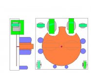
Wouldn't a groundplane set up as a circle like this, as either a solid copper panel or thick style PCB..circular, set off the chassis two inches...the ground connects would be a short one and a half inches...all components would be situated "around" this groundplane...all connects would be short....Ideas??
___________________________________________Rick...........
Attachments
I guess coming from an antenna design background...can you say collinear array?...., I see E & I fields everywhere...it would even out ground patterns as each component would be equadistant(sp?) from each other, the green ground from the power-cord would pop up in the very middle....no one component would see a different ground...I'm seeing fields (Dead people?) everywhere........this setup would eliminate that potential variable.
___________________________________________Rick...........
___________________________________________Rick...........
Re: Goundplane layout theory
I already do something similar, though not exactly like that. The last project I did had four subsystem circuit boards: front end and driver, positive rail supply, negative rail supply, and active screen volatge regulator. Each one used a "modified dead bug" construction where connection pads are etched into the copper cladding, which serves as a local ground plane. Each board is insulated from the metal chassis. The ground planes of each board are connected individually directly to the DC neutral, which is then connected to the chassis via diodes wired anti-parallel (i.e. "69" style) and paralleled by a 10R resistor and 0.1uF capacitor. The chassis being connected to the third wire safety ground.
This semi-star grounding works very well, and makes for dead quiet. Only way you can tell if it's on is by the glow of the tubes.
Richard Ellis said:Wouldn't a groundplane set up as a circle like this, as either a solid copper panel or thick style PCB..circular, set off the chassis two inches...the ground connects would be a short one and a half inches...all components would be situated "around" this groundplane...all connects would be short....Ideas??
I already do something similar, though not exactly like that. The last project I did had four subsystem circuit boards: front end and driver, positive rail supply, negative rail supply, and active screen volatge regulator. Each one used a "modified dead bug" construction where connection pads are etched into the copper cladding, which serves as a local ground plane. Each board is insulated from the metal chassis. The ground planes of each board are connected individually directly to the DC neutral, which is then connected to the chassis via diodes wired anti-parallel (i.e. "69" style) and paralleled by a 10R resistor and 0.1uF capacitor. The chassis being connected to the third wire safety ground.
This semi-star grounding works very well, and makes for dead quiet. Only way you can tell if it's on is by the glow of the tubes.
This is certainly interesting.
I have tried doing spectral analysis (with VERY limited test gear) on my hand-built amp with both complex and simple signals in the audio band to see if there is any non-linearity being introduced by external fields (I was curious)
I couldn't find anything besides the signal, with identifiable distortion. However I did not look above 40Khz.
Miles: I like your description of your grounding scheme. I have made some tube ccts that are pretty quiet, but not so quiet that you coul'n't hear some hum if you put your ear to the speaker. I guess I have just accepted that as the price of using H/V power for tubes.
Richard: what I find interesting about your idea is that is echos something I read in a review of the Lyra Conniseur preamp (HiFi+ calls it the best preamp ever made). Apparently, the active circuits are arranged in a cube with precise spacing between every component. measured capacitances and inductances are factored into the component selection. Seems they are using 0.1% components and they claim this results in the lowest distortion (and the pricetag of $20,000!).
Jess
I have tried doing spectral analysis (with VERY limited test gear) on my hand-built amp with both complex and simple signals in the audio band to see if there is any non-linearity being introduced by external fields (I was curious)
I couldn't find anything besides the signal, with identifiable distortion. However I did not look above 40Khz.
Miles: I like your description of your grounding scheme. I have made some tube ccts that are pretty quiet, but not so quiet that you coul'n't hear some hum if you put your ear to the speaker. I guess I have just accepted that as the price of using H/V power for tubes.
it would even out ground patterns as each component would be equadistant(sp?) from each other
Richard: what I find interesting about your idea is that is echos something I read in a review of the Lyra Conniseur preamp (HiFi+ calls it the best preamp ever made). Apparently, the active circuits are arranged in a cube with precise spacing between every component. measured capacitances and inductances are factored into the component selection. Seems they are using 0.1% components and they claim this results in the lowest distortion (and the pricetag of $20,000!).
Jess
JesseG said:Apparently, the active circuits are arranged in a cube with precise spacing between every component. measured capacitances and inductances are factored into the component selection. Seems they are using 0.1% components and they claim this results in the lowest distortion (and the pricetag of $20,000!).
Well, they need to do something to justify a price tag like that.

Seriously, ground planes are a great idea and well worth the trouble.
JesseG said:Miles: I like your description of your grounding scheme. I have made some tube ccts that are pretty quiet, but not so quiet that you coul'n't hear some hum if you put your ear to the speaker. I guess I have just accepted that as the price of using H/V power for tubes.
I didn't say there wasn't any hum. I o'scope about 6.0mVp-p of a 60Hz sine wave at the output. Really, who cares? I certainly do not listen with my ears right up against the speeks. I suppose I could've gotten 30 car batteries, connected them in series for the HV, and eliminated all the hum, but really...
Off topic but I now want a shirt that says "I see E & I fields".I guess coming from an antenna design background...can you say collinear array?...., I see E & I fields everywhere...it would even out ground patterns as each component would be equadistant(sp?) from each other, the green ground from the power-cord would pop up in the very middle....no one component would see a different ground...I'm seeing fields (Dead people?) everywhere........this setup would eliminate that potential variable.
Other than that this topic is beyond me. I just use a simple star ground...no problems yet.
Richard Ellis said:...it would even out ground patterns as each component would be equadistant(sp?) from each other, the green ground from the power-cord would pop up in the very middle....no one component would see a different ground.
I prefer not to think about 'ground'. As far as the operation of the amplifier is concerned, ground and the green wire from the power cord are rather uninteresting. It's better to think current loops.
Lynn Olson on current loops
Thinking current loops would have probably prevented the mistake this DIY builder made:
spot the mistake
Groundplanes can get you good current loop control because the AC return currents are free to choose the path of minimum induction, and the induction of a wide flat conductor is minimal. Of course there are plenty of opportunities to shoot yourself in the foot with a ground plane too.
Ground (bounce) and more on current loops
And more on ground planes / current loops
Originally posted by Gesse
I have tried doing spectral analysis (with VERY limited test gear) on my hand-built amp with both complex and simple signals in the audio band to see if there is any non-linearity being introduced by external fields
What would be a mechanism by which an external field could cause non linear distortion?
What would be a mechanism by which an external field could cause non linear distortion?
I have absoultely no idea!
Most;ly, I was just playing around looking at the capabilities of the spectrum analyser, but it crossed my (small and untrained) mind that I might look for components in the spectra that should not be there.
The amp in question is built on an open chassis with no shielding on the sides or bottom. In this it is not different from a thousand tube amps built on a sheet of steel or aluminium sitting on a wooden frame. It seems to work just fine.
THANK YOU for the references to the grounding articles in you post. I have been mystified by this for years. maybe now I will be able to 'see' these current loops like you pros do
Jess
Re: Spot the Error
That's not quite right. What he did was make his DC neutral a length of bare wire that makes a closed loop around the periphery of the chassis. It makes a nice, one turn pick-up coil for ripple residuals coming from the DC supply. What he should have done is make one central neutral connection, and run a return to that for each DC return path.
It's what I avoided by making each connection from the local circuit board ground planes directly to the DC neutral, as opposed to making the wiring job "neater" by connecting the ground planes in a "daisy chain" manner. It would have been neater, with fewer wires running hither and yon, but would have made a loop. All that gets you is more noise. It's especially bad when you have a gain stage with a large Av, which is what I had since I did a cascode LTP voltage amp/phase splitter.
Richard Ellis said:I think I got it .....wouldn't the signal zero act as an antenna....doesn't look like a half wave dipole to you???folded over of course?/B]
That's not quite right. What he did was make his DC neutral a length of bare wire that makes a closed loop around the periphery of the chassis. It makes a nice, one turn pick-up coil for ripple residuals coming from the DC supply. What he should have done is make one central neutral connection, and run a return to that for each DC return path.
It's what I avoided by making each connection from the local circuit board ground planes directly to the DC neutral, as opposed to making the wiring job "neater" by connecting the ground planes in a "daisy chain" manner. It would have been neater, with fewer wires running hither and yon, but would have made a loop. All that gets you is more noise. It's especially bad when you have a gain stage with a large Av, which is what I had since I did a cascode LTP voltage amp/phase splitter.
hint
You're looking at the right part of the circuit, but it gets much worse. How does the first capacitor get charged?
power supply cuircuit
Call me a geek, but I've often fantasized how it would be if one could actually see EM fields in any frequency range. I'd say it would be a real eye openener, not to mention the cool special effects!
In the splintercell games you have EM goggles, who knows maybe some day ...
Re: hint
Current thinking among some scientists is that migratory birds may actually be able to see the magnetic field lines of the earth. To migrate from, say, Canada to South America they just follow the highway in the sky!
It should be possible to mimic that with a stereo EMF sensor feeding goggles or a HUD. I'm not sure I'd want to see what surrounds me everyday though!
Back on topic; I designed a PCB for a chip amp (I'm no circuit board designer, just trying it out). It was essentially a single layer design for power, input and output. I used the bottom layer as a solid copper groundplane. Whooo boy! Get that sucker near any electromagnetic field, within 1" of its own power supply, within 2" of a wall wart, 6" from a flourescent light etc. and it hums. If I had made it more portable I could easily use it as an EMF detector!
I had used the same single layer layout without a groundplane and the amp was dead quiet even sitting right on top of the power supply box. I guess all that proves is I have a lot to learn about designing attennas... er, I mean PCBs.
arend-jan said:...
Call me a geek, but I've often fantasized how it would be if one could actually see EM fields in any frequency range. I'd say it would be a real eye openener, not to mention the cool special effects!
In the splintercell games you have EM goggles, who knows maybe some day ... [/B]
Current thinking among some scientists is that migratory birds may actually be able to see the magnetic field lines of the earth. To migrate from, say, Canada to South America they just follow the highway in the sky!
It should be possible to mimic that with a stereo EMF sensor feeding goggles or a HUD. I'm not sure I'd want to see what surrounds me everyday though!
Back on topic; I designed a PCB for a chip amp (I'm no circuit board designer, just trying it out). It was essentially a single layer design for power, input and output. I used the bottom layer as a solid copper groundplane. Whooo boy! Get that sucker near any electromagnetic field, within 1" of its own power supply, within 2" of a wall wart, 6" from a flourescent light etc. and it hums. If I had made it more portable I could easily use it as an EMF detector!
I had used the same single layer layout without a groundplane and the amp was dead quiet even sitting right on top of the power supply box. I guess all that proves is I have a lot to learn about designing attennas... er, I mean PCBs.
- Status
- This old topic is closed. If you want to reopen this topic, contact a moderator using the "Report Post" button.
- Home
- Amplifiers
- Tubes / Valves
- Groundplane layout theory