As I understand it two major features determine the performance of a particular tube in CF circuits.
1. gm: High gm leads to low Zout (about 1/gm if I recall correctly).
2. current capacity: High current capability helps to drive capacitive load and any input current requirements of the following stage.
Is that approximately correct?
Ideally one wants the lowest Zout and highest possible drive current but the question is how do we determine what is really good enough for the given application.
For example a tube with a gm of 1200 umhos running at 1mA would be considered, I believe, a very poor choice in a full range preamp that would be driving an unknown power amp.
However the Zout would be less than 1kohms which would generally be enough to deliver most of its signal voltage to even a worst case SS power amp with 10 to 20k input impedance. The problem would seem to be the low current capability which would most likely cause significant high frequency losses.
But suppose that the application is a subwoofer output where nothing below 120Hz or so would be needed. In this case is it not possible that the given tube would provide adequate performance?
So the overall question is how do we calculate the necessary current and transconductance capabilities for adequate performance in a given application.
So you ask, why bother... just use a better tube? The reason is efficient use of available materials and intellectual satisfaction.
mike
mashaffer said:As I understand it two major features determine the performance of a particular tube in CF circuits.
1. gm: High gm leads to low Zout (about 1/gm if I recall correctly).
2. current capacity: High current capability helps to drive capacitive load and any input current requirements of the following stage.
Is that approximately correct?
Pretty much. rk= (Rp + rp)/(1 + u) (Where Rp= 0 for the most part with CFs)
Ideally one wants the lowest Zout and highest possible drive current but the question is how do we determine what is really good enough for the given application.
For example a tube with a gm of 1200 umhos running at 1mA would be considered, I believe, a very poor choice in a full range preamp that would be driving an unknown power amp.
However the Zout would be less than 1kohms which would generally be enough to deliver most of its signal voltage to even a worst case SS power amp with 10 to 20k input impedance. The problem would seem to be the low current capability which would most likely cause significant high frequency losses.
The cathode follower is always at its best when you need a Lo-Z source impedance for a Hi-Z load. If it's as you describe, gm= 1.2mA/V and Ipq= 1.0mA, it'll promptly roll over and die for any significant load impedance. When using a follower driver, after determining the load current for whatever purpose, then apply the "Rule of Five" from SS practice (States that the collector current of the driving stage should be five or more times the base current of the driven stage.) and make Ipq=> 5 X Il. As for max current from the CF, it's approximately: Imax~= Vpp / rp. This serves as a rough guesstimate as to what you can expect from it.
As for what tubes make the best CFs, these will usually be the medium-u triodes (6J5, 6SN7, 6C4, 12AU7, 12BH7) or possibly some of the higher-u types with decent current handling (12AT7, 6BQ7A, 6BK7). The low current types like the 6SF5, 12AX7, 6AV6, 6SL7 seldom are good choices. If you need higher voltage gain, then small signal pentodes, run as pentodes, make excellent followers even if they are a bit more complex.
Thanks guys, I think we are on the right track.
SY;
This is precisely what I want to calculate. Lets say the subwoofer amplifier is going to have a 3V peak maximum signal at 10k input impedance with normal input and cable capacitance. How do we calculate drive current for 3kHz bandwidth (just to give us a little wiggle room)? Do we have to go back to the definition of capacitance and calculate charging time at particular currents?
mike
SY;
If we assume a 2 volt input sensitivity (that’s RMS; peak will be about 2.8V) for our power amp, the signal current needed to drive the 1000pF load capacitance to the full voltage while maintaining the 90kHz bandwidth is about i = 1.6mA.
This is precisely what I want to calculate. Lets say the subwoofer amplifier is going to have a 3V peak maximum signal at 10k input impedance with normal input and cable capacitance. How do we calculate drive current for 3kHz bandwidth (just to give us a little wiggle room)? Do we have to go back to the definition of capacitance and calculate charging time at particular currents?
mike
That's exactly it. But... you'll have to have an ENORMOUS capacitance and/or a pathological source impedance to have a problem with that sort of limited bandwidth. Do it as an exercise anyway, but you'll find that with any reasonable choice of tube and interconnect, your bandwidth will be grossly better than you need.
Thanks SY. BTW I look forward to seeing your website at full strength. It looks interesting.
From Slew Rate Explained
an equation is developed for the current requirements to avoid slew rate limitating. If I understand this all correctly their equation should provide what we need to know.
I = C * 2 * pi * F * Vpeak
They got this taking into account the definition of slew rate and capacitor charging current.
Putting in our numbers of .001uf input capacitance, 3kHz max frequency and 3V peak input signal I get 56.5uA. Does that look about right? If so it seem that just about any small signal triode should do fine regardless of reputation for this specific application. Is that right?
mike
I used the 10k example as a worst case estimate. In any case I have picked up a bunch of NOS and used tubes so maybe there might be something in there.
6DT6 pentode
6BZ6 pentode
6GM6 pentode
6JC6 sharp-cutoff pentode
6EW6 pentode
6CB6A pentode/triode
6CG8A pentode/triode
6GH8A pentode/triode
6EB8 pentode/triode
6BL8 pentode/triode
6U8 pentode/triode
I weeded out the obviously inappropriate ones from the list like damper diodes.
I plan on using a pair of 6N1Ps for the 60Hz to 200Hz bandpass channels. If I end up buying something for the sub out filter would you suggest one of the same, 12AT7, 6922 or something else?
To determine the distortion would you use the 10k load line on the standard plate curves (like you were designing a CC gain stage)?
mike
You got it. Pretend the load is in the plate, calculate the distortion, then divide it by the feedback factor (about the tube's mu).
ECC88 is a standard and excellent choice. For your service, a 12AT7 will also work fine. Pentodes make great CFs, but at a higher parts count (need to swing the screen with the cathode).
ECC88 is a standard and excellent choice. For your service, a 12AT7 will also work fine. Pentodes make great CFs, but at a higher parts count (need to swing the screen with the cathode).
Thanks Geek, will make a note of that use for those tubes, that could come in handy.
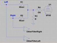
As to the 6FH5 my main concern is that using a single triode to mix the two channels might compromise the channel separation in the other filters. The plan is to feed all three frequency range filters from the volume pots which should be fine but doing single channel sub ties the L&R together through the input resistors.
mike
Thanks SY,
Actually my concern was using a single triode with both left and right channels feeding its single grid as shown.
Any possibility of causing crosstalk problems with the stereo filters and amplification stages that will be fed off of the same input?
Grid stopper adequate or do you think other more heroic measures will be necessary?
As far as microphonics goes operating at line level with gain <1 should make that less of a problem than it would be otherwise I suppose.
I guess I can always "bread board" it and do a quick and dirty measurement of crosstalk. The 6FH5 intrigues me because of its combination of relatively high mu (not important in this application of course) and high gm and current capabilities. Seems like it might be a nice little tubie.
mike
A dual triode won't cause any separation problems. Remember, the plates are grounded at AC.
Actually my concern was using a single triode with both left and right channels feeding its single grid as shown.
Any possibility of causing crosstalk problems with the stereo filters and amplification stages that will be fed off of the same input?
6FH5 will work fine assuming it isn't microphonic (which many tubes of its class tend to be) and you take care to prevent it from oscillating.
Grid stopper adequate or do you think other more heroic measures will be necessary?
As far as microphonics goes operating at line level with gain <1 should make that less of a problem than it would be otherwise I suppose.
I guess I can always "bread board" it and do a quick and dirty measurement of crosstalk. The 6FH5 intrigues me because of its combination of relatively high mu (not important in this application of course) and high gm and current capabilities. Seems like it might be a nice little tubie.
mike
Attachments
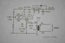
SY.....to cut a long story short.....I've been using this config (below) in studio stuff for donkeys (25)years. Fooling everyone because it's so darned simple and sounds sharp.....double section ECC88 paralled parafeeding into a Sowter stepdown. The catch is an excellent quality coupling cap and worst of all, the transformer spec. The small caps on the B+ is testament to the RF nature of the ECC88 tube. As expected, layout is somewhat critical and must be kept to pins. I've omitted the CCS as to avoid any noise contribution, already -90dBu down.
Current through tube is pretty well what you find.
I could have used a split cathode resistor i.e bootstrapped to g1's to up the input Z, but in every case I found thd (already dead low) somewhat unpredictably increases vs. load Z. Perhaps I should revisit this problem. Notice the actual o/p Z !
richj
Attachments
Rich, what do you use for that 68u cap? Of course, as you know, any CCS noise is divided down by the parallel combination of the transformer Z and the cathode source Z. Not that you'd want a CCS there anyway, the load impedance is dominated by the transformer.
mike, if you model each of your sources as a Thevenin equivalent, you'll see how much separation suffers (it won't be much). Regarding the care and feeding of RF triodes, use a grid stopper, a cathode stopper, and bypass the heater pins individually to the closest possible chassis points with some 10nF ceramics. Make sure the plate is bypassed to signal ground with short leads and a high-quality cap so the tube won't think it's got a load at VHF.
mike, if you model each of your sources as a Thevenin equivalent, you'll see how much separation suffers (it won't be much). Regarding the care and feeding of RF triodes, use a grid stopper, a cathode stopper, and bypass the heater pins individually to the closest possible chassis points with some 10nF ceramics. Make sure the plate is bypassed to signal ground with short leads and a high-quality cap so the tube won't think it's got a load at VHF.
SY said:Rich, what do you use for that 68u cap? Of course, as you know, any CCS noise is divided down by the parallel combination of the transformer Z and the cathode source Z. Not that you'd want a CCS there anyway, the load impedance is dominated by the transformer.
-> Yup quite right. Somewhere I should have a graph of output level vs. loading plus thd thrown in. Will dig it out.
cap is a. ICW wopper size 160V low leakage polypropy'e. Your end I should think Cornell Dublier should have something sim.
http://www.icwltd.co.uk/claritycap/pwa/size.html
rj:-
- Status
- This old topic is closed. If you want to reopen this topic, contact a moderator using the "Report Post" button.
- Home
- Amplifiers
- Tubes / Valves
- Good enough CFs