Hi, this is my first post on DiyAudio, although I've been lurking awhile.
I have a set of power and output transformers that I obtained from my grandfather some time ago and I want to put them to use rather than them gathering dust in the shed! They were originally used in a pair of Mullard 5-10's that he constructed in the early 1960's. I'm after a few suggestions for potential projects.
Transformers are:
2 x Partridge P4013 power transformers
300-0-300 @135mA, 2 x 6.3v ct@2A, 1 x 0-5-6.3 @2A
2 x Partridge P3667 output transformers
8k primary (with 6k taps), ??? secondary - there are two windings but the label has rubbed off
1 x Partridge P4014 output transformer (C-core)
8k primary with 43%UL taps, 4 secondary windings (16 ohm with all in series)
If I had two of the P4014 I would go for the Baby Huey (EL84) that seems to be quite popular, but I'm out of luck. I don't really want to use EL84's in pentode mode with the P3667 transformers, so what to do?
Would a triode connected EL34 PP be possible using the 8k P3667's? I should be able to get ~400V out of the transformer with solid state rectification (current might be marginal?), and the P3667's are rated for 15W.
Any suggestions are welcome") This would be my first valve amp project, but I have built a few solid state amps.
This would be my first valve amp project, but I have built a few solid state amps.
Steve
I have a set of power and output transformers that I obtained from my grandfather some time ago and I want to put them to use rather than them gathering dust in the shed! They were originally used in a pair of Mullard 5-10's that he constructed in the early 1960's. I'm after a few suggestions for potential projects.
Transformers are:
2 x Partridge P4013 power transformers
300-0-300 @135mA, 2 x 6.3v ct@2A, 1 x 0-5-6.3 @2A
2 x Partridge P3667 output transformers
8k primary (with 6k taps), ??? secondary - there are two windings but the label has rubbed off
1 x Partridge P4014 output transformer (C-core)
8k primary with 43%UL taps, 4 secondary windings (16 ohm with all in series)
If I had two of the P4014 I would go for the Baby Huey (EL84) that seems to be quite popular, but I'm out of luck. I don't really want to use EL84's in pentode mode with the P3667 transformers, so what to do?
Would a triode connected EL34 PP be possible using the 8k P3667's? I should be able to get ~400V out of the transformer with solid state rectification (current might be marginal?), and the P3667's are rated for 15W.
Any suggestions are welcome
This would be my first valve amp project, but I have built a few solid state amps.Steve
I'm not sure about this, but I think the 6K primary tap could be used as a UL connection on the P3667 transformer. I was not able to find specific information on your transformers with a quick google, but this should work.
I don't think this transformer is suitable for use with EL34 because the plate currents for good performance with an EL34 are significantly higher than with the EL84, and 8K does not represent an optimum load for EL34 in triode connection either.
Triode connected EL84 will give you 7 - 8 watts output depending on operating point chosen, and IMO 7 watts of triode connected EL84 power sounds very good. (I have an amp based on Scott iron that is in this power range.)
Steve,
The 6 KOhm taps could be used for UL connections, but the amount of local NFB applied to the screen grids will be different than that seen with the "typical" 40% UL tap. As I mull things over, it seems this UL connection will be very triode like. I expect a good deal less than 2X pure triode delivers.
"El Cheapo" circuitry requires approx. 360 V. of B+. You should be able to obtain that from the 300-0-300 winding using 5R4 rectification and CLC filtration. The pair of 6.3 V./2 A. filament windings will provide plenty of heater current for a 12AT7 splitter driver, an 'AL5 B- rectifier and a pair of 6V6 family O/P tubes.
I can understand why you would want to put Partridge transformers to good use, they should be excellent.
I would agree with Kevin's view that the current needed to run EL34s could be too much for those OP trannies. I expect you can get excellent performance from EL84s in UL PP.
I would agree with Kevin's view that the current needed to run EL34s could be too much for those OP trannies. I expect you can get excellent performance from EL84s in UL PP.
Thanks for your responses guys, all very helpful. I had thought about using the 6k taps for UL mode but taps are effectively 85% (measured using ratio of winding resistances) rather than the standard 20% or 43%, too far away for me to be confident of using them in this manner. Triode connected EL84's would be less "risky" but only 5W - maybe parallel PP using the 6k taps might work (normal recommended load for a single triode connected pair being 10k)?
The PP EL34 triode mode I was thinking of was the "alternative" one mentioned in the Mullard data sheets and in "Mullard circuits for audio amplifiers" (I have the second edition from 1960), where a 8-12k load is used with a 235 ohm shared cathode resistor (no bypass). Maximum power output is reduced a little from that achieved with the more usual 5k load, about 13W, but distortion is also reduced to <1%. I thought I might get away with this mode of operation given the output transformers seem fairly rugged (they weigh 3.2 pounds each).
I suppose if all else fails I could consider pentode operation, using some of the more modern (compared to the 5-10) circuits floating around.
tikiroo said:Thanks for your responses guys, all very helpful. I had thought about using the 6k taps for UL mode but taps are effectively 85% (measured using ratio of winding resistances) rather than the standard 20% or 43%, too far away for me to be confident of using them in this manner. Triode connected EL84's would be less "risky" but only 5W - maybe parallel PP using the 6k taps might work (normal recommended load for a single triode connected pair being 10k)?
The PP EL34 triode mode I was thinking of was the "alternative" one mentioned in the Mullard data sheets and in "Mullard circuits for audio amplifiers" (I have the second edition from 1960), where a 8-12k load is used with a 235 ohm shared cathode resistor (no bypass). Maximum power output is reduced a little from that achieved with the more usual 5k load, about 13W, but distortion is also reduced to <1%. I thought I might get away with this mode of operation given the output transformers seem fairly rugged (they weigh 3.2 pounds each).
I suppose if all else fails I could consider pentode operation, using some of the more modern (compared to the 5-10) circuits floating around.
There's no risk at all, running at the 15% tap will simply give you something just a little closer to triode mode operation than the oft recommended 20%. (EL84 only, don't do this with the alternative circuit you mentioned above.)
You might get away with the alternative configuration you describe as the combined plate current will be in the vicinity of 70mA which is in the same territory as is typical for a conservatively run pair of EL84.
Hi,
If you went for the Baby Huey with pentode mode outputs you can expect the output impedance to be adequately low. The Plate to Plate feedback does an excellent job of lowering output impedance to levels comparable to a cathode follower (hard to believe but true). Don't know exactly what output impdance the Baby Huey claims, but I have used this approach in another amp and it works fine.
Shoog
Steve,
The "Baby Huey" idea is excellent. Gingertube, who did the design work, is a fellow "Aussie". Comparative geographic closeness can't hurt.
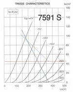
Another possibility is a triode wired "El Cheapo Grande". Triode wired 7591s will work on those 6 Ohm taps. Run the "idle" current for a PP pair as "hot" as possible, consistent with O/P trafo limits. You will have to SS rectify the B+ in ECGs, using your power trafos. Also, combination bias is indicated on the PP pair to safely allow 330 KOhm grid leak resistors. That value keeps 12AT7 splitter driver gain up and works well with 100 nF. coupling caps. from the splitter.
The "Baby Huey" idea is excellent. Gingertube, who did the design work, is a fellow "Aussie". Comparative geographic closeness can't hurt.
Another possibility is a triode wired "El Cheapo Grande". Triode wired 7591s will work on those 6 Ohm taps. Run the "idle" current for a PP pair as "hot" as possible, consistent with O/P trafo limits. You will have to SS rectify the B+ in ECGs, using your power trafos. Also, combination bias is indicated on the PP pair to safely allow 330 KOhm grid leak resistors. That value keeps 12AT7 splitter driver gain up and works well with 100 nF. coupling caps. from the splitter.
Eli Duttman said:Steve,
The "Baby Huey" idea is excellent. Gingertube, who did the design work, is a fellow "Aussie". Comparative geographic closeness can't hurt.
Another possibility is a triode wired "El Cheapo Grande". Triode wired 7591s will work on those 6 Ohm taps. Run the "idle" current for a PP pair as "hot" as possible, consistent with O/P trafo limits. You will have to SS rectify the B+ in ECGs, using your power trafos. Also, combination bias is indicated on the PP pair to safely allow 330 KOhm grid leak resistors. That value keeps 12AT7 splitter driver gain up and works well with 100 nF. coupling caps. from the splitter.
Eli, you've sold me on the "El Cheapo Grande", I get maximum use out of the power transformers and the sonic benefits of PP triodes. The 7591's look nicer than EL84's as well
. I should be able to run the idle current at 50-60 mA. Just a couple of quick questions before I read the 58 pages of the El Cheapo thread:-What do mean by "ECGs" when talking about solid state rectification?
- By combination bias do you mean a single cathode resistor, or something else?
Thanks for your help, also the others that have made suggestions.
Steve
What do mean by "ECGs" when talking about solid state rectification?
ECG = "El Cheapo Grande"
By combination bias do you mean a single cathode resistor, or something else?
Combination bias is a method that uses both a RC network in the cathode circuitry and a negative supply in the grid circuitry. As the name suggests, it's a combination of "fixed" and cathode bias.
Combination bias has several virtues. The cathode RC network stabilizes the operating point, which allows the use of grid leak resistor values greater than that usually seen, when a negative bias supply is employed. Obtaining the bulk of the bias from a negative supply avoids "wasting" B+ rail Volts. Use a well matched pair of "finals" and a single, shared, RC cathode bias network. I recommend 100 Ohms and 470 μF. in the bias network. A single trim pot. serves to set the "idle" current in the PP pair.
-------------------------------------------------------------------------------------------------------
A B+ rail voltage of approx. 390 is to be expected from a 300-0-300 V. rectifier winding in combination with SS rectification. The 'T7 should have 200-220 V. on its anode and IB should be 3 mA. Losses in a "check valve" decoupling network are under 2 V. A total of 62 KOhms will load the 'T7 anodes. Obtain that total from a 50 KOhm inductive wirewound resistor and a 12 KOhm Carbon film part.
The power trafo has 3 filament windings. Phase up and connect in parallel the "indentical" pair. This parallel pair will energize the heaters of the 3 signal tubes and the heater of an indirectly heated vacuum rectifier that slows B- rise down. The 3rd filament winding will be voltage multiplied along the lines of the 2nd schematic shown here. A total of 6 multiplier stages will be used. Schottky diodes will be in the 1st 5 stages and a vacuum rectifier in the 6th stage. You will tap the multiplier after 3 stages to get the instant on C- bias supply. All 6 stages form the B- supply needed by the splitter/driver circuitry.
What sort of signal source(s) are planned for use with the ECG monoblocks?
Has consideration been given to volume control, channel balance, and source selection?
Do you have something like a 6X4, 6X5, or 7Y4 in your parts pile?
BTW, 7591 screen grids exhibit some toughness. So, use a 180 Ohm Carbon composition resistor to tie each of the 2X g2 connections to the plate.
Fantastic response Eli, you've answered all my questions before
I asked them! Plenty of information to get me started. I'll have a go drawing some load lines using the triode curves for the JJ 7591
I had thought of doing that, but couldn't work out the required voltage for B- from the circuit diagram, thanks for the tip. What value capacitors should be used in the voltage multiplier?
Just a CD player, I don't own any vinyl. So plenty of signal level.
Not yet. Probably just a basic volume pot.
My "parts bin" (at least as far as tube gear goes) consists of the transformers, a few tubes salvaged from the original amplifiers (Mullard and Miniwatt EF86, ECC82/83, EL84, EZ81) and....that's it! I'm sure I'll be able to track down a suitable rectifier valve.
A week ago my knowledge of vacuum tube electronics was next to nothing, isn't the internet amazing!
I asked them! Plenty of information to get me started. I'll have a go drawing some load lines using the triode curves for the JJ 7591
Eli Duttman said:
The 3rd filament winding will be voltage multiplied along the lines of the 2nd schematic shown here. All 6 stages form the B- supply needed by the splitter/driver circuitry.
I had thought of doing that, but couldn't work out the required voltage for B- from the circuit diagram, thanks for the tip. What value capacitors should be used in the voltage multiplier?
What sort of signal source(s) are planned for use with the ECG monoblocks?
Just a CD player, I don't own any vinyl. So plenty of signal level.
Has consideration been given to volume control, channel balance, and source selection?
Not yet. Probably just a basic volume pot.
Do you have something like a 6X4, 6X5, or 7Y4 in your parts pile?
My "parts bin" (at least as far as tube gear goes) consists of the transformers, a few tubes salvaged from the original amplifiers (Mullard and Miniwatt EF86, ECC82/83, EL84, EZ81) and....that's it! I'm sure I'll be able to track down a suitable rectifier valve.
A week ago my knowledge of vacuum tube electronics was next to nothing, isn't the internet amazing!
If those 8K Partridges are push-pull OPTs, that would work just great with 6CK4 finals. I was considering this myself, but all the junk box pickin's suggested doing a 6BQ6GTB design instead, since I had the OPT and power xfmr for that.
You get the advantages of avoiding any sort of screen supply, 6CK4s are real triodes, so you don't have to triode pentodes. They seem to work real good here. Since this was designed for TV vertical deflection duty, they should also be pretty tough.
6CK4 PP Loadline
You get the advantages of avoiding any sort of screen supply, 6CK4s are real triodes, so you don't have to triode pentodes. They seem to work real good here. Since this was designed for TV vertical deflection duty, they should also be pretty tough.
6CK4 PP Loadline
Steve,
The triode curves on the JJ data sheet provide useful info. Notice that when the plate to cathode differential is 400 V. and IB is 30 mA., the negative grid bias is between 20 and 25 V. A drop of 6 V. will occur thru the shared 100 Ohm bias resistor at that "idle" current in each of the PP pair. Somewhat less that 20 V. has to come from the C- supply. Approx. 7.5 V. can be expected from each Schottky diode stage of the voltage multiplier. So for bias, 4 stages will prove adequate. 270 KOhm grid leak resistors and a 100 KOhm trim pot. seem to be satisfactory. The wiper of the trim pot. connects to the "bottom" of both grid leak resistors. The ends of the trim pot. connect between C- and ground.
An additional 3 Schotkky diode multiplier stages will be quite sufficient to drive the B- rail. At the low current draw in the negative rails, 330 μF. 'lytics will crush the ripple fundamental, in spite of the 1/2 wave situation. However, large filter caps. cause ripple overtones to be present. Those overtones will be killed by inserting RF chokes (RFCs) in the lines leading away from the voltage multiplier. A final reservoir cap. will complete each of the negative rails.
The EZ81/6CA4 rectifiers you inherited are "boffo" for the B- delay role. Connect the RFC that leads from the 7th multiplier stage to the vacuum rectifier's cathode. Connect the rectifier's anodes in parallel to a 47 μF. reservoir 'lytic.
Miles,
That 6CK4 does seem to have a good fit, but they might be a bit hard to find in this neck of the woods. Also the drive voltage swing required is a lot higher than for the 7591's so I would have to re-think the driver stage which is probably beyond me at this stage!
Eli,
Thanks for the further information, I think I have everything I need now. I'll draw up a schematic and start tracking down the required bits and pieces.
I've had a go at the load lines for the triode connected 7591. At a Va of 370, 8k a-a load and idle current of 45mA per tube, max power is 9W (8W class A). The 6k taps look like they will be too heavy a load, although as mentioned previously there is the possibility of using them as "ultralinear" taps to squeeze a bit more power out of the tubes.
Attachments
Steve,
You may have observed that things would improve, if the B+ rail voltage were to be higher. If you are willing to invest (not too much) in some additional "iron", you can get more B+ Volts from the trafos already in your possession.
Use the "identical" pair of 6.3 VAC filament windings to extend the rectifier winding ends. Use the remaining filament winding in the series boost connection, on the primary side. Such an arrangement will get the B+ rail above 400 V.
You may have observed that things would improve, if the B+ rail voltage were to be higher. If you are willing to invest (not too much
) in some additional "iron", you can get more B+ Volts from the trafos already in your possession.Use the "identical" pair of 6.3 VAC filament windings to extend the rectifier winding ends. Use the remaining filament winding in the series boost connection, on the primary side. Such an arrangement will get the B+ rail above 400 V.
Thanks for the suggestion. Alternatively, the power transformer primaries have 10-0-200-220-240 taps. If I use our nominal 240V on the 0-220 volt taps, all secondary voltages would be boosted by 9%, getting B+ over 400V. Although all the heaters would all be running at 6.9V which might be a problem.
Va of 400V would give 11W power (6W class A), probably not enough to notice the difference, and about the same as I would achieve if I used the 6k (85%) taps for ultra-linear operation.
I'll keep to the standard arrangement for now, but these are options for experimentation later on.
Va of 400V would give 11W power (6W class A), probably not enough to notice the difference, and about the same as I would achieve if I used the 6k (85%) taps for ultra-linear operation.
I'll keep to the standard arrangement for now, but these are options for experimentation later on.
tikiroo,
I'm in Adelaide but was a farm kid from Kybybolite and went to Naracoorte High School which is only 50 klicks up the road from "the Mount" where you are.
If you need advice, supplier recommendations etc. or if you ever get to the "big smoke" and want to hear a Baby Huey give me a buzz.
I'm actually running some $3500 Audio Space 300B Push Pull Monoblocks at the moment. The owner has asked me to see if I can't improve them a bit - which they need. The Baby Huey leaves these supposedly Hi End things for dead. You don't need to spend a fortune to get great sound.
My "Baby Huey", Eli's "El Cheapo", Poindexters "Music Machine", SY's "Red Light District" (and possibly some others) are all aimed at this end of the DIY market. Getting great sound without spending huge bucks.
Home most evenings and weekends. 08-8269-3539.
Cheers,
Ian (Gingertube).
Hi Gingertube,
I really appreciate the offer of advice (and the phone number!). I'll be sure to give you a call if I get stuck.
I'm just getting together a list of all the bits and pieces I need. I should be able to scrounge high voltage power supply and other capacitors from work out of scrapped industrial DC drives - as you have guessed I'm trying to do this on the cheap!
Are there any local suppliers of valves etc you would recommend, or is overseas (eg Antique Electronic Supply) the best value?
Steve
Steve,
Australian Suppliers rave:
Do a web search for Bob's Tube Audio.
Bob Rundle is an ex Electronic Engineer and Tech. College Instructor who I first met nearly 35 years ago when he was running a company which designed and built ECG machines (I did my electronics training in medical electronics at the Royal Adelaide Hospital). He is now semi retired and runs an on-line tube store. Trades on e-bay as "qch" and opens his store (Jaybird Electronics) on Port Road, Friday and Saturday afternoons. There is an email contact on his e-bay listings. The store openings are as much a social event (gab fest for tube nutters) as a real commercial thing. He does most buisiness on-line. You can contact him on 08-8447 7411. He is a Hammond agent for trannies and chassis, and a JJ Electronics agent for tubes. Also has a range of capacitors, tube sockets, parts kits etc he gets in from Taiwan and a constantly changing range of NOS and used tubes which all go through his AVO tube tester before being offered for sale. Often has stuff like tube testers, vintage radios etc for sale on commision.
There is also Evatco (also on the web) who are now in Brisbane. Evatco are a fair bit more expensive but have a larger range and keep most of it in stock.
I buy most of my stuff from Bob but have also used Evatco quite a bit. Overseas suppliers I've used are PartsConnexion and Antique Electronic Supplies, had good service and quick delivery from both.
For example, I recently needed 2 matched quads of EH 300B's. It was cheaper for me to get them from PartsConnexion in Canada (who had them on special) than to get them from Evatco who are the local ElecroHarmonix agents. On the other hand when I needed 2 matched quads of Gold Lion Re-Issue KT88 it was cheaper to get them from Evatco (by the time I factored in delivery and GST).
Cheers,
Ian
- Status
- This old topic is closed. If you want to reopen this topic, contact a moderator using the "Report Post" button.
- Home
- Amplifiers
- Tubes / Valves
- Potential project for some inherited transformers