Hi,
I've just saw that my CCS power supply is loading... I try without load it give exactly 12V, when I place a 125R resistor as load it give me ~3.5V
All because of a 470R resistor that I attached between 2 capacitor to (I was thinking) flatten the ripples. By bypassing it it's return to normal, even under load..
Could someone explain me why it does so and should I get rid of the resistor ?
(The schematic of the PSU and the CCS itself is attached to the message.. the resistor in question is R1 on the schematic)
Attachments
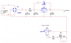
That's a bizarre circuit. You've got two regulators essentially in series, one on either side of the source. (why?) First, U2 is limiting the available voltage to U1 to only 12 volts. U1 will not supply 12 volts because it needs more voltage across it. Unloaded it's barely limping through U1. There is also too much total series resistance that will limit current.
If this were my supply, I'd use only one active regulator, not two. I'd eliminate R1 and C2 and make C1 much larger. U2 is all you need for 12 volts. If you want the extra .6 volts, put a silicone diode in U2's common lead to raise the output to 12.6V.
If you really want the adjustable feature, then use U1 where U2 is now. Put the adjustment pot on the ADJ terminal, not on the IN or OUT terminal. I hope this makes sense.
- Status
- This old topic is closed. If you want to reopen this topic, contact a moderator using the "Report Post" button.