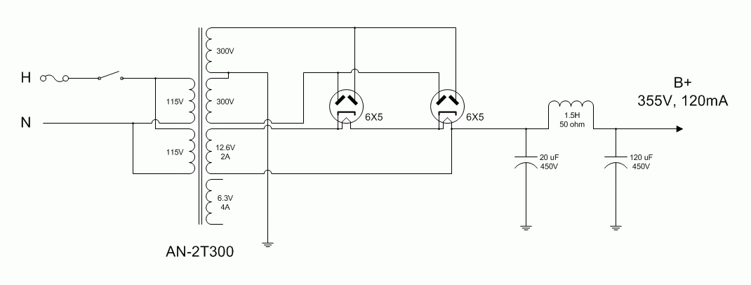
I've come across a couple old (1945 vintage) 6L6GA tubes. They're beautiful with their ST bottles and smoked glass sides. I'd like to build a stereo single ended amp out of them. In the same box came a few 6X5GT rectifiers. I'd like to use them in the power supply. I think I'm going to need a separate 6X5 to feed each 6L6GA?
Any hints, or pointers to a recommended schematic?
Any hints, or pointers to a recommended schematic?
TubeLab's Simple SE is appealing. I've taken a good look at it. I like building kits where someone else has already done the design and proven the circuit is sound. It doesn't hurt that many others have already built it as well. I'm not completely married to the 6X5, it's just that I happen to have them.
What kind of power transformer would I need to run a pair of 6L6GA in the Simple SE board? George seems to like the Allied 6K7VG, but I'm thinking the B+ would end up too high for the 6L6GA.
What kind of power transformer would I need to run a pair of 6L6GA in the Simple SE board? George seems to like the Allied 6K7VG, but I'm thinking the B+ would end up too high for the 6L6GA.
George seems to like the Allied 6K7VG, but I'm thinking the B+ would end up too high for the 6L6GA.
YES, big time! I plugged a pair of crusty old 6L6GA's into one of my amps, and they REALLY didn't like it. They were on the verge of runaway, and would slip into uncontrolled red glow mode whenever they wanted to. The old 6L6 (metal) and the 6L6GA's want about 380 to 390 volts with cathode bias to remain in spec. I have used 400 to 410 without issue, but the Allied 6K7VG can make 440 to 460 with a 5AR4. I have been using some surplus HP power transformers for amps like this, but I don't have any more left. They are 650 VCT.
I have a Hammond 272JX (600VCT) on my bench. Hammonds are known for running high. I will hook it up and try it over the weekend if I can find the time.
Guys,
The AnTek AN-3T325.pdf toroidal power trafo should do nicely for this project. Wire the 6X5 heaters in series and connect them to the 12.6 VAC winding.
The AnTek AN-3T325.pdf toroidal power trafo should do nicely for this project. Wire the 6X5 heaters in series and connect them to the 12.6 VAC winding.
I'm wondering if the AnTek AN-3T275 would be a better fit, and just use a 5AR4 rectifier. My problem with the AnTek transformers is that I never know where to buy them, other than wait for one to show up on eBay. Can I just call the guys and order one? Do they sell direct? I guess I should try sometime...
I'm also looking at the Hammond P-T270HX. AES has them on their website for $63. But, I've read that sometimes the Hammond 200 series have a mechanical hum and that kind of stuff really turns me off.
I'm also looking at the Hammond P-T270HX. AES has them on their website for $63. But, I've read that sometimes the Hammond 200 series have a mechanical hum and that kind of stuff really turns me off.
I might offer a word of advice on this idea, since I've had something similar brewing in my head for a long time. 6L6's are great tubes, but what's also nice is that there are the following equivalents:
12L6
25L6
35L6
50L6
etc.
With a simple 2 pole rotary switch and a couple of cheap transformers (a 50L6 needs very little heater current), you could have essentially a limitless supply of NOS power tubes. For example NOS 50L6's at Antique are $6!
-Paul
12L6
25L6
35L6
50L6
etc.
With a simple 2 pole rotary switch and a couple of cheap transformers (a 50L6 needs very little heater current), you could have essentially a limitless supply of NOS power tubes. For example NOS 50L6's at Antique are $6!
-Paul
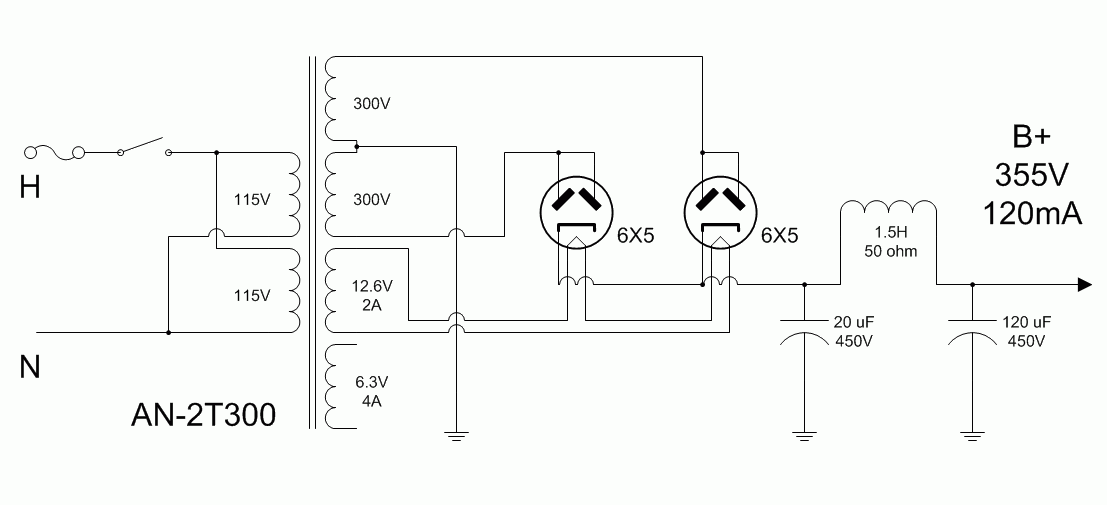
Ah, I see. I was thinking of the 5AR4. I guess I should always check the datasheets first. Is this better? It seems it may be more customary to connect the plates of the twin diodes together as shown, rather than the way I did in my first attempt. I'm not sure it makes any difference either way.

I believe I need to think harder about the expected B+ voltage and my intended bias point. The 6L6GA is only rated for 19 watts, and my PSU schematic is showing 21.3. Of course, the 355 volt number could be way off. I'm not exactly sure how to calculate the B+ using multiple rectifier tubes.

I believe I need to think harder about the expected B+ voltage and my intended bias point. The 6L6GA is only rated for 19 watts, and my PSU schematic is showing 21.3. Of course, the 355 volt number could be way off. I'm not exactly sure how to calculate the B+ using multiple rectifier tubes.
audiowize said:I might offer a word of advice on this idea, since I've had something similar brewing in my head for a long time. 6L6's are great tubes, but what's also nice is that there are the following equivalents:
12L6
25L6
35L6
50L6
etc.
-Paul
No, these are NOT equivalents! It IS true in most cases that equivalent tubes have similar numbers... but in this case the 6V equivalent is 6W6. The 35L6 is rated a little lower than the others - 6W6, 12W6, 12L6, 25L6, 50L6 are very close except for heater voltage. A power pentode with maybe 10W plate dissipation, 150V maximum screen voltage.
Ty_Bower said:Ah, I see. I was thinking of the 5AR4. I guess I should always check the datasheets first. Is this better? It seems it may be more customary to connect the plates of the twin diodes together as shown, rather than the way I did in my first attempt. I'm not sure it makes any difference either way.

I believe I need to think harder about the expected B+ voltage and my intended bias point. The 6L6GA is only rated for 19 watts, and my PSU schematic is showing 21.3. Of course, the 355 volt number could be way off. I'm not exactly sure how to calculate the B+ using multiple rectifier tubes.
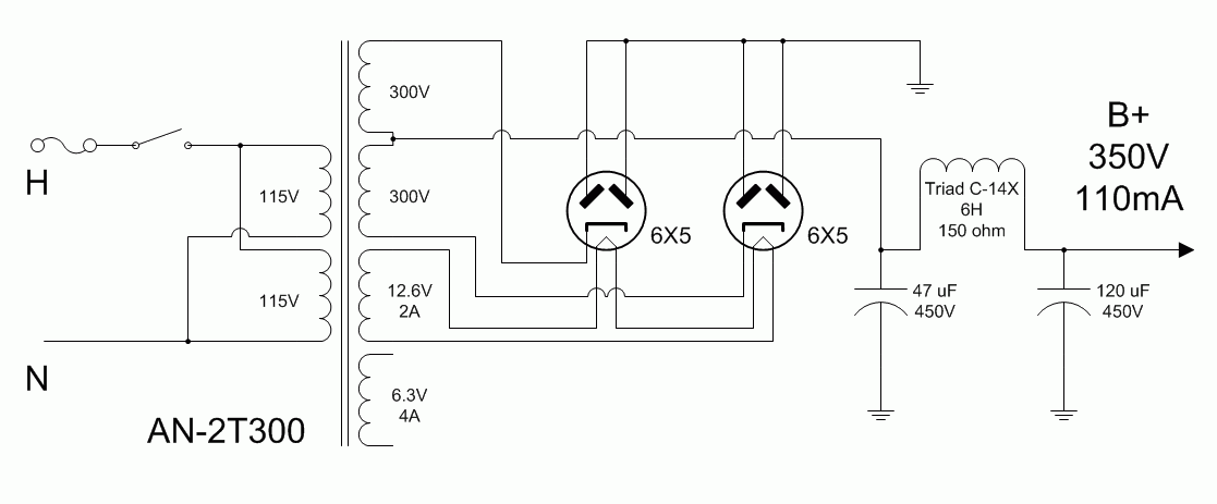
That PSU schematic looks OK. You can bring the B+ rail voltage down by making the 1st filter cap. 4.7 μF. Keep the ripple level low by using a 6 H./200 mA. Triad C-14X choke from Allied.
John Atwood's experience suggests that using both plates inside a single envelope in parallel, as your drawing indicates, is best.
Look at the 6L6G data sheet. The 19 W. plate dissipation limit is design center. You can safely go as high a 20 W., without trouble. Don't simultaneously "push the envelope" of both max. dissipation and anode voltage.
Also, keep the fact that g2 makes a contribution to power O/P, when UL mode is employed, in mind.
Questions about the Simple SE board: What's the biggest (diameter) capacitor that can fit at C1 and C2? Mouser obsoleted the part suggested on the TubeLab parts list (C1) and there is no Mouser suggested part for C2.
Could I use these Mouser parts? They seem kinda expensive, though.
647-UPW2W470MRD
647-UPW2W101MRD
Could I use these Mouser parts? They seem kinda expensive, though.
647-UPW2W470MRD
647-UPW2W101MRD
SE 6L6G Amp
BTW I just love my SE 6L6G amp.
I use the Tungsol Re-Issue 6L6G
which is a 6L6GC in a coke bottle glass.
I also use the Genelex Re-Issue KT66
both are great but different sounding.
My voltages are too high for your use.
I drive mine with Mullard 6P5GTs with
an unbypassed cathode resistor.
Choke loaded and grid choke for 6L6G.
LCLC filter and 5V4GT rectifier.
Silk 5K OPT and TVC input.
DanL
Ty,
I've got an assembly idea. You have discrete rectifiers on each side of the full wave CT PSU. IMO, you will have fewer headaches mounting the pair of 6X5s close to, but off of, the PCB. Ground all 4 6X5 anodes. Connect a 6X5 cathode to each end of the 600 VCT. Take the "raw" B+ from the CT of the rectifier winding. Now, you have a single line to the PSU filter and the space the 5AR4 socket usually goes into can be occupied by filter capacitance.
I've got an assembly idea.
Like this?

I like it. I had already figured the pair of 6X5 had to be mounted off the board anyway. I'm trying to figure out how to make the chassis mount rectifiers and the PC mount power tubes "look" right in the finished amp, but then again I've never been much of one to worry about the final cosmetics.
Do you think the 600VCT transformer is the right size to get about 350 VDC, 55 mA per tube (110 mA total)?
- Status
- This old topic is closed. If you want to reopen this topic, contact a moderator using the "Report Post" button.
- Home
- Amplifiers
- Tubes / Valves
- Need ideas - 6L6GA & 6X5GT
