Not sure if this is quite the right forum, but I'll give it a try anyways.
I built a guitar amp that uses JFETs for switching. This is my first time trying them, I used vactrols LDRs before. When I built it all on the breadboard it works fine as well, however in circuit, no such luck.
The switching driver circuit works fine, but the JFETS are not doing there job. I was very careful not to overheat them when soldering, using a heat sink clip. I read that JFETS don't have source/sink polarity so I just have them arbitrarily in one direction.
I am using the Fairchild KSK30YTA here is the datasheet http://www.fairchildsemi.com/ds/KS/KSK30.pdf
any ideas?
thanks
d1
Hi,
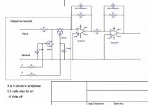
This shows a 2SK152 in a similar arrangement to yours. The FET becomes "shorted" i.e. at it's lowest resistance when the gate is made slightly positive with respect to the source. 0.3 Volts is about as high as you can go, above that and the gate will start to conduct like a forward biased diode. This slight positive bias helps reduce the on resistance instead of leaving the gate at zero volts. To cut the FET off, i.e. make it go open circuit the gate is brought negative with respect to the source ( for these N Channel types ), the data sheet says -5 as a maximum for these. The 2SK152 are rated 15V gate/source but are only 15 volt D/S devices.
What voltage swing do you see on the grid of the valve both above and below ground under full drive, if it goes negative you have a problem I think in using FET's like this.
Many (many many many ) years since I last worked on valve gear--- TV.' s PL509 PY500A etc
The 2SK152 go down to about 30 ohms the 2SK30 a bit higher, about 70 ohms I think. Going from memory I have seen some FET's with different pin outs, gate at one end as well.
Attachments
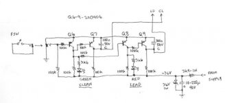
Well, well - A London Power "Standard" preamp.
I built a full "Standard" Amp (from Kevin's TUT5) just recently. I used J201 J-Fets for the switching and it worked perfectly. I can ONLY conclude that you had the JFets incorrectly loaded (Drain and Source reversed perhaps - The Source pin must go to the ground).
This is one of the sweatest guitar preamps I've ever heard. Clean is lovely and the Lead Channel with Lead Gain set at about 3 to 4 allows you to effectively drive the amount of distortion off the guitar - play soft and it comes through Clean, wack it a bit harder and it breaks up nicely. With Lead Gain at 10 you have as much overdrive as you would ever need.
One caution: In the switching circuit use cheap LEDs. - NOT ultra bright LEDs. When the annunciating LEDs are meant to be off there is still a leakage path back through the cascaded transistor Base Emitter junction and base resistor. If you use ultra bright LEDS you will find that the LED never goes completely off when you change channels.
I used it as per the posted schematic for several weeks BUT eventually redesigned the switching board so that I could continue to use the same LEDs - Ultrabright Green and Blue in their own Silver Bezels - BUT have them go completely off when changing channels.
Complete Thread on the build - lots of pictures and the redesigned switching board circuit I used are on the London Power, Power Scaling Forum. Worth registering there as you can then query Kevin direct.
Cheers,
Ian
d1,
Yes it means -36V from Gate to Source. When gate is at 0V the "switch" is ON when the gate is at -36V then the "switch" is OFF. (JFETs are depletion mode devices like a tube, they are ON till you bias them OFF).
The "bias" MUST be applied between gate and source. The source MUST go to 0V. With -36V on the gate then the FET is OFF and the drain "floats" (high impedance). With 0V on the gate the FET is ON and the drain gets switched to the source connection which is 0V.
The link you posted for the data sheet doesn't work but I see you stated in an earlier post that the data sheet shows Vgds was quoted as -50V. That is -50V from gate to drain AND -50V from gate to source.
The -36V to gate will be fine. Someone suggested above that that was way too much voltage and would damage your devices. If the device was a MOSFET then that would be true BUT the JFET can handle it fine.
The J201 (what I used) data shows:
VDG (Drain Gate) = 40V
VGS (Gate Source) = -40V
The devices Kevin originally suggested (2SK369 IIRC) are 50V rated parts BUT I have had absolutely no problem using the 40V rated JFET.
- Status
- This old topic is closed. If you want to reopen this topic, contact a moderator using the "Report Post" button.
- Home
- Amplifiers
- Tubes / Valves
- JFET Switching on my tube amp