hi all,
need advice.
what would be the optimum Rload resistor for my dac tube output stage, im getting cracking sound from high level volume music, this is without the resistor,
i did try with 1M resistor, but distortions..
i have posted in digital section but not getting any advice..
>hope might get a reply from this forum..thanks.
>best regards,
>tone.
Attachments
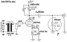
I am not familiar with this particular circuit, but I would suggest that if the output is fed into a SS amp then the resistor should be 50-100k and if into headphones then probably 10k or less. If the problem is overloading you could replace the resistor with a pot of the same value and take the output from the wiper.
However, if you are getting distortion and crackling I would also check the 1uf coupling capacitor, as it might be leaky and passing DC.
However, if you are getting distortion and crackling I would also check the 1uf coupling capacitor, as it might be leaky and passing DC.
Tone,
The purpose of the resistor is only to stop high voltage from appearing on the output. 1M will do. A bit lower is probably OK too, but if you go much lower you will start to "load" the previous stage.
I think that this design will not work well into a low impedance.
Cheers,
The purpose of the resistor is only to stop high voltage from appearing on the output. 1M will do. A bit lower is probably OK too, but if you go much lower you will start to "load" the previous stage.
I think that this design will not work well into a low impedance.
Cheers,
If this amp is feeding into a main amp the chances are that the resistor is unnecessary, as in the main map the input will feed across a load resistor anyway, possibly a volume pot - only if there is an isolating cap will a load resistor here be useful.
As far as any distortion/cracking is concerned, I think that this will caused elsewhere in the circuit, possibly the coupling cap, dry soldering joints, even noisy anode resistors (seems to be two in parallel) possibly...
As far as any distortion/cracking is concerned, I think that this will caused elsewhere in the circuit, possibly the coupling cap, dry soldering joints, even noisy anode resistors (seems to be two in parallel) possibly...
DAC.
Hi,
Not a digital expert but I find this setup rather errr... odd.
At the input of the xformer you have I/V conversion, the xformer steps up 1:15, than you have the tube stage where you take the output from the anode?? This ends up again in a highish Zo...
Looks odd to me.
Cheers,")
Hi,
Not a digital expert but I find this setup rather errr... odd.
At the input of the xformer you have I/V conversion, the xformer steps up 1:15, than you have the tube stage where you take the output from the anode?? This ends up again in a highish Zo...
Looks odd to me.
Cheers,
If this amp is feeding into a main amp the chances are that the resistor is unnecessary, as in the main map the input will feed across a load resistor anyway, possibly a volume pot - only if there is an isolating cap will a load resistor here be useful.
Real bad advice if one want to disconnect DAC/cdplayer and amp now and then....
Or if one touches the center of the RCA cable...
It will give a plop from here to Tokyo and possibly the ( if SS ) amp will be dead too afterwards.
Old design techniques weren't invented for fun.
Jean-Paul
dac
hi all,
1M resistor works.or should i use 500K?
hi bournville : u were right, the 1uf solen caps was leaking or something is wrong, replace the caps with new one..works fine..thanks.no more cracking sound.
Hi frank: what u would recommanded? i couldnt find any one tube for both channel circuit for the dac..so i use my preamp circuit for the dac.pls advice..thanks.
btw:it seem the dac is lack of bass, would a higher cathode caps helps>?
best,
tone.
1 M is OK. Maybe you could check some tube output stages on these sites. Don't forget that the TDA1541A puts out more current than other DAC chips !
http://users.podolsk.ru/boga/Images/DAC_Buffer.gif
http://www.ndh.net/home/kboehm/T-DAC-P2.htm
http://www.ahfartaudio.com/6021W2doc.htm
http://www.megabaud.fi/~jtolonen/ga/tubedac/part1.html
http://home.netcom.com/~wa2ise/radios/tubedac.htm
http://users.podolsk.ru/boga/Images/DAC_Buffer.gif
http://www.ndh.net/home/kboehm/T-DAC-P2.htm
http://www.ahfartaudio.com/6021W2doc.htm
http://www.megabaud.fi/~jtolonen/ga/tubedac/part1.html
http://home.netcom.com/~wa2ise/radios/tubedac.htm
odd design?
Hi Frank
to tweak my Sony I first thought about maybe using something similar. Your comment about Zout (which makes a very reasonable point) made me somewhat uncertain about wether or not to consider this topology seriously (as I´m completely new to tubes I´m still a bit without direction).
What do You guys think about about this interesting circuit (BTW great tubes site IMO - look at the other stuff too!). Basic conception is very similar to what "tone" posted:
An I/V Converter for current-output DACs
(Click on the green headlines to view the schematics)
Do You think an additional buffer could help when loading this DAC with about 50k to 100k (certainly it would lower Zout but could this improve sound too...)?
What would YOU do?
originally posted by fdegrove
Not a digital expert but I find this setup rather errr... odd.
At the input of the xformer you have I/V conversion, the xformer steps up 1:15, than you have the tube stage where you take the output from the anode?? This ends up again in a highish Zo...
Looks odd to me.
Hi Frank
to tweak my Sony I first thought about maybe using something similar. Your comment about Zout (which makes a very reasonable point) made me somewhat uncertain about wether or not to consider this topology seriously (as I´m completely new to tubes I´m still a bit without direction).
What do You guys think about about this interesting circuit (BTW great tubes site IMO - look at the other stuff too!). Basic conception is very similar to what "tone" posted:
An I/V Converter for current-output DACs
(Click on the green headlines to view the schematics)
Do You think an additional buffer could help when loading this DAC with about 50k to 100k (certainly it would lower Zout but could this improve sound too...)?
What would YOU do?
Re: dac
Is there any dc current through that 50 ohm I/V resistor? If there is, it will also flow through the transformer primary causing it's inductance to go down the toilet, and with it your bass response. You would need to put a resonably large cap inseries with the transformer primary to block the DC.tone said:btw:it seem the dac is lack of bass,
DAC
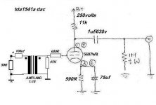
Tone, your tube is under biased. For 250v, try Rp 11K, Rk 590ohm with 75uf bypass. That'll get you 10ma per section. It's highish gain at ~23db, plus the transformer gain, it's probably pretty hot. Also you may consider ac coupling the bottom of the trans primary, as Philips dacs have a 2 - 4V DC on the output, easily saturating some transformers. Audio Note and others get by without doing that because 1865 has very low dc volts on the current out.
Tone, your tube is under biased. For 250v, try Rp 11K, Rk 590ohm with 75uf bypass. That'll get you 10ma per section. It's highish gain at ~23db, plus the transformer gain, it's probably pretty hot. Also you may consider ac coupling the bottom of the trans primary, as Philips dacs have a 2 - 4V DC on the output, easily saturating some transformers. Audio Note and others get by without doing that because 1865 has very low dc volts on the current out.
Hi Circlotron, I realised what you posted was correct, I mistakenly read you wanted a cap between chip and primary. Most DAC's don't accept that.
What Scott Nixon says got in my mind too. The DC level of TDA1541A is too high to couple direct.
That's why I deleted my own post.
What Scott Nixon says got in my mind too. The DC level of TDA1541A is too high to couple direct.
That's why I deleted my own post.
DAC.
Hi,
Just wondering, could a gapped xformer be used here?
Or is the current level just too high?
Cheers,
Hi,
What Scott Nixon says got in my mind too. The DC level of TDA1541A is too high to couple direct.
Just wondering, could a gapped xformer be used here?
Or is the current level just too high?
Cheers,
Re: DAC.
Hi,
Cheers,
Hi,
It will depend a lot on the primary DC resistance. There is a very low value resistor there, which hopefully will take the "lions share" of the current.fdegrove said:Hi,
Just wondering, could a gapped xformer be used here?
Or is the current level just too high?
Cheers,
Cheers,
dac
hi all,
Circlotron:a resonably large cap inseries with the transformer primary to block the DC.
>would 100uf ok? or is it too big..
scottnixon:what do mean by ac coupling the bottom of the transformer primary?
circuit attached..pls advice.if anything is wrong b4 i do the mod.
thanks guys for teh help..
tone
Attachments
Almost
The cap needs to go on the bottom of the trans primary, kind of a parafeed arrangement, as a rough example. Take the cap off the input to the trans, flip it around and insert into the ground node of the primary and 50 ohm, + to trans primary low side and the neg to ground with the 50 ohm. Hope that makes sense.
The cap needs to go on the bottom of the trans primary, kind of a parafeed arrangement, as a rough example. Take the cap off the input to the trans, flip it around and insert into the ground node of the primary and 50 ohm, + to trans primary low side and the neg to ground with the 50 ohm. Hope that makes sense.
- Status
- This old topic is closed. If you want to reopen this topic, contact a moderator using the "Report Post" button.
- Home
- Amplifiers
- Tubes / Valves
- dac tube output stage..pls help.