SY said:Tube Dude, you may wish to tell this to the writers of every textbook I have. They all show output (collector) impedance of a degenerated bipolar CCS as 1/hoe + Re(hfe), though some put in a factor of 2 to approximate the increase in hfe with lower current.
You can derive the expression yourself from first principles. You can assume that Re >> re for most practical values of Re. Since 1/hoe is generally << Re(hfe), the latter term dominates.
The collector output impedance of a bipolar transistor, even without emitter resistor, is a not perfect constant current source, like a penthode valve.
So, the intrinsic collector output impedance is much bigger than the emitter resistor and dominates.
The product (hfe)Re gives you the impedance looking in the base of the transistor.
In any way, a CCS with a 200 Ohms emitter resistor and a typical hfe of 100 will have a 20.000 Ohms output impedance, that's is typical of a transistor without emitter resistor....
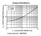
""The slope of the curve in this operating region represents the reciprocal of the transistor's collector or output resistance Rc, i.e., Slope = Ic/Vce = 1/Rc. This means that in this region of the curve, the output resistance is relatively high (between 10-50 kÙ). An average Rc value of 30 kÙ in this region may be assumed.""
http://www.ecelab.com/vce-ic-curves.htm
SY said:The same feedback factor that increases the base impedance also increases the collector impedance. It's not surprising that you see the hfe(Re) term in both expressions.
I agree absolutely!
But as the intrinsic collector output impedance of the transistor is high in opposition of the base, makes the necessity of a big emitter resistor, less stringent, for a useful collector output impedance.
That way, we can end with less power dissipation, in the base voltage reference.
But, if one want to use a big emitter resistor and the supply have voltage headroom enough... why not!
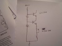
Well, here's where I'll disagree a bit. Let's look at a 2N3904, for example, since it's common and pretty typical. 1/hoe (the collector resistance) is only about 15-20k. That's not really quite enough even for a cathode resistor. That's why you need the degeneration, which in this case takes things well over a meg.
Now, you might argue that we could use a high voltage NPN like an MJE340 or TIP50, which have a collector resistance more like 150k. But the degenerative power is less because of the lower hfe.
Let's compare. With that 13k resistor, the 2N3904 (or better yet, a slightly higher voltage NPN) will have a source resistance of 15k + (150)(13k) = 1.97M. The MJE340 will have a source resistance of 150k + (30)(13k) = 540k. That may be good enough, but the higher hfe of the smaller unit, along with its lower capacitance and higher ft, would push me in that direction for these low currents even if one (correctly, I think) relegates the threefold improvement in Rout as being moot.
Ok. Lets put some things in perspective .
In the case of the circuit of Burnedfingers.
We have a Long Tail Pair of 6SL7, the intrinsic cathode resistance will be 1/Gm around ~600 Ohms, as we have two in parallel we will end with a ~300 Ohms nod, in the point of junction of the two cathodes.
Taking the 2N3904 as the worst value of collector output impedance of 20kohms, isn't this value considered good enough as a CCS for feeding a ~300 Ohms impedance.
It's ~70 times greater and the use of a small emitter resistor will make this relation even greater...
The original component in there was something like a 50k resistor, right? And the balance with symmetrical plate resistors is mediocre.
There's a reason for that. Your 300 ohm figure is only true for 100% degeneration. The actual looking-in impedance at the cathodes is the sum of the load resistance and plate resistance divided by mu + 1.
There's a reason for that. Your 300 ohm figure is only true for 100% degeneration. The actual looking-in impedance at the cathodes is the sum of the load resistance and plate resistance divided by mu + 1.
SY said:The original component in there was something like a 50k resistor, right?
Right! ... At the end of the day, the transistor current source will be noisy than the humble resistor.
But, the beauty of the tubes, is that we don't have to deal with the nonlinear output capacitance of the transistor, that change during the voltage swing.
This effect is strongly observed in the output circuits of the CD players that use transistors as muting devices, even if in the CD, the impedances into play are much lower.
For that reason, when feeding a LTP from a transistor CCS, I always put a resistor in series with the collector, for isolation purposes...
For a diffamp tail I always use cascode BJT current source.
A single transistor current source has 2 problems.
1st its output impedance is limited by Early Effect. This can be mitigated by using higher reference voltage on the base and hence higher emitter (current set) resistor in the emitter. As a "rule of thumb" you need an absolute minimum of 450mV being developed across the emitter resistor but more is better (This sufficiently addresses thermal effects and starts to mitigate Early Effect).
2nd the single transistor current source output impedance drops significantly as you increase frequency due to device capacitance. This will show up as lack of detail in the top end and loss of image. The way to address this is to use a cascode.
Aside: In an early "Baby Huey" I ran a single transistor current source, Red LED reference, for the front end diff amp. Changing to a cascode gave an immediately noticable improvement to top end detail, smoothness and stereo imaging.
The frequency limitation is the main reason why I've never been a fan of LM317 and similar devices as a current source in low level signal areas. They just don't present the output impedance to a high enough frequency due to output capacitance.
For the same reason (output capacitance) it is important to keep wiring between the CCS and the tube cathodes "short and sweet" to minimise stray capacitance.
Cheers,
Ian
PS - If you decide that your bookshelf can "suffer" one reference work on Solid State that you can look up the stuff talked about in this thread, then may I recommend the book which is the Trade School text book for all our electronics apprentices:
"The Art of Electronics" Paul Horowitz, Winfield Hill
ISBN 0 521 37095 7
calculating a BJT ccs ...
#24 #25
Hi Forum, Jorge and SY
It is wrong to tell something like a typical transistor constant current source has...
Better have a look at the datasheet.
http://www.datasheetcatalog.com/
hoe is the admittance of the current source with Re (emitter resistor) = 0.
You can read this value from the attached graph.
You can see that 1/hoe is ≈100KΩ at 1,3mA.
You can calculate the resistance of the constant current source
in the following way:
((Re x Ie/UT)+1)/hoe = r output
In this formula
Re is the emitter resistor
Ie is the emitter DC current
UT ≈ 40mV (Silicon)
hoe is the collector and emitter admittance, see attachment.
r output is the resistance of the constant current source.
Now start calculating, you'll be surprised!
Kind regards,
Darius
Attachments
Re: calculating a BJT ccs ...
Hi, Darius
Not surprised at all, I already know that the resistance looking in the collector of a Bipolar Junction Transistor, even without emitter resistor, is very high and can be considered a "almost perfect" CCS.
At 1,3 mA the intrinsic emitter resistance is ~ 20 Ohms, if as stated early in this thread, the output collector resistance was the product of (hfe)X(Re), for a output resistance of 100Kohms we must have a hfe of 5.000...")
Best Regards
oldeurope said:
Now start calculating, you'll be surprised!
Hi, Darius
Not surprised at all, I already know that the resistance looking in the collector of a Bipolar Junction Transistor, even without emitter resistor, is very high and can be considered a "almost perfect" CCS.
At 1,3 mA the intrinsic emitter resistance is ~ 20 Ohms, if as stated early in this thread, the output collector resistance was the product of (hfe)X(Re), for a output resistance of 100Kohms we must have a hfe of 5.000...
Best Regards
#36
Thanks for your reply, Jorge
Please calculate it, and you'll be surprised.
Thanks for the example.
Just forget SY's formula, it is totally wrong here.
Kind regards
Darius
Thanks for your reply, Jorge
Tube_Dude said:
Hi, Darius
Not surprised at all, I already know that the resistance looking in the collector of a Bipolar Junction Transistor, even without emitter resistor, is very high and can be considered a "almost perfect" CCS.
...
Best Regards
Please calculate it, and you'll be surprised.
Tube_Dude said:
Hi, Darius
...
At 1,3 mA the intrinsic emitter resistance is ~ 20 Ohms, if as stated early in this thread, the output collector resistance was the product of (hfe)X(Re), for a output resistance of 100Kohms we must have a hfe of 5.000...
Best Regards
Thanks for the example.
Just forget SY's formula, it is totally wrong here.
Kind regards
Darius
#37
calculate the result and you'll see that you are far far away from the truth.
This is why I wrote: “You'll be surprised.”
Kind regards
Darius
Hello SY,SY said:...The formula I gave, which is derived in most basic texts, is an approximation for Re>>re.
calculate the result and you'll see that you are far far away from the truth.
This is why I wrote: “You'll be surprised.”
Kind regards
Darius
Tube_Dude said:But, the beauty of the tubes, is that we don't have to deal with the nonlinear output capacitance of the transistor, that change during the voltage swing.
This effect is strongly observed in the output circuits of the CD players that use transistors as muting devices, even if in the CD, the impedances into play are much lower.
For that reason, when feeding a LTP from a transistor CCS, I always put a resistor in series with the collector, for isolation purposes...
Long-long time ago people used so called "Reactive tubes" for frequency modulation...
- Status
- This old topic is closed. If you want to reopen this topic, contact a moderator using the "Report Post" button.
- Home
- Amplifiers
- Tubes / Valves
- Replacing a cathode resistor with a CCS