Hi there,
I'm trying to build a guitar amp..
I'm working on a preamp section (tone stack)
What I want to do is to have the possibility to switch between two equalization circuit (without duplicating all the stuff).
The image attached could explain it better.
I want to use a relays to remotely switch between first eq and another one with mid -scooped and vice versa.
I'm a bit afraid on how to choose the right relay..I'm worried about high tension on the relays contact from the 2 resistor.
the value of the tension out of the filtering cap is 380V and the tube is 12ax7. how do I have to choose this relay? any hints/clue?
Is there another way to do this mod?
anything more to add (bleeding resistor or whaterver else?)
I thought about blocking DC with a capacitor before entering R27 and R27scoop but I think it will impact on the tone...what do u think?
Thanks a lot for your precious help.
Krusty
Attachments
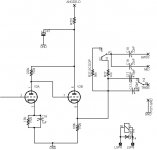
The relay doesn't carry DC because of C17, C18, C19. But adding another cap will not change the sound as long as it is substantially bigger than C17/18/19, such as being 1uF for instance.
All you need to be sure of the that the relay's physical size is Ok for the potential on its contacts with respect to the coil, i.e., don't use a tiny PCB mount reed relay. Any relay good for AC mains switching will work.
All you need to be sure of the that the relay's physical size is Ok for the potential on its contacts with respect to the coil, i.e., don't use a tiny PCB mount reed relay. Any relay good for AC mains switching will work.
Well actually I thought that "half" of the relay (DPDT) will carry DC ..I mean the side directly attached to the resistor R27 and R27-SCOOP.
Can you please explain me better what do u mean with " for the potential on its contacts with respect to the coil" in your post?
If my coil is 12V and the voltage out of the cathode is 300V what I have to check on the relay?
Any part suggested?
The cap I thought to add is between R26 and R27/R27-SCOOP. Are you sure it doesn't change tone if 1uF because it has a very low roll off frequency?
Thanks again!
Krusty
There is NO DC current flowing through the relay... it can not get through the capss on the one end.... current always flows in a complete loop...
The 12V is likely the coil voltage to swith the relay on... in reality a bit less is adequate..., What you need to make sure is your
Max switching voltage rateing is enough...
As an example I have on my desk a relay with a max switching voltage of 440AC/125VDC 8A with 24V coil with 1440 ohm coil resistance, which would require 16mA at 24V coil voltage...
It also has some other important specs
Dielectric strenght: between coil and contacts 5000VAC (1min)
between contact sets 2500VAC (1min)
between open contacts 1000VAC (1min)
and it has a surge rateing of 10kV...
The relays contact rating is not the really important part. What you need to pay close attention to is that the 300V on the contacts doesn't flash over to the coil, as may happen if the relay is physically very small.
BUT any relay with 300V rated contact will take this into account anyway.
BUT any relay with 300V rated contact will take this into account anyway.
Steerpike said:The relay doesn't carry DC because of C17, C18, C19. But adding another cap will not change the sound as long as it is substantially bigger than C17/18/19, such as being 1uF for instance.
All you need to be sure of the that the relay's physical size is Ok for the potential on its contacts with respect to the coil, i.e., don't use a tiny PCB mount reed relay. Any relay good for AC mains switching will work.
Steerpike said:The relays contact rating is not the really important part. What you need to pay close attention to is that the 300V on the contacts doesn't flash over to the coil, as may happen if the relay is physically very small.
BUT any relay with 300V rated contact will take this into account anyway.
Actually this is not strictly true as you will quickly find out when you try to switch low level audio signals through a relay designed to handle high currents and voltages. Relay contacts require a certain minimum current through them to assure good performance - below this and you get lots of distortion. Design so that no high dc voltages are ever presented the relay!
You are switching audio, only two things are of concern:
1. Do not switch DC, isolate all signals with coupling caps and provide a dc path to ground for that cap that does NOT include the relay.
2. Select a relay with low contact resistance that is designed to switch low level signals.
I use scores of relays in my design work every day (ATE) and have learned the hard way what works and what doesn't.
For long term reliability reed relays will be better than most open frame types particularly at relatively low signal levels. There are types that are rated 100V which should be adequate for any audio voltage which should be encountered in your pre-amplifier.
Pickering, Omron, Panasonic and others make good relays.
Do not switch DC, isolate all signals with coupling caps and provide a dc path to ground for that cap that does NOT include the relay.
But what do u mean related to my schematic included?
I mean do I have to put a cap on the signal taken from the cathode and how can I provide a path to ground? with a resistor? or what?
Sorry but I'm quite a newbie so I need things to be explain with some example at first

And then how can I choose the capacity of that cap?
Thanks again.
Krusty
Yes, cap from cathode and a resistor (1M or so) to ground, not a bad idea to put a small resistor (say 1K) in series with the relay contacts in the event that despite your best efforts some charging currents flow through the contacts upon closure. (this is topology dependent.)
- Status
- This old topic is closed. If you want to reopen this topic, contact a moderator using the "Report Post" button.
- Home
- Amplifiers
- Tubes / Valves
- DC offset and relays