OK.
Just trying to get a handle on numbers here. For whatever reason, I'm not able to suss this out.
HK A250 amp- Stuart Hegeman design, using positive feedback to the phase splitter (split load).
I need to see if I can figure out the gain of the phase splitter stage, with this arrangement, in order to figure out global open-loop gain of the amp. Need to know how I need to tune the feedback loop, to use a transformer with only an 8-ohm output tap... the feedback will naturally, be from the 8 ohm tap, instead of from the 16 ohm tap.
My initial guess was just to factor the voltage... and wound up with a tentative plan to use about a 10K ohm resistor instead of the 15K. BUT- I would like to know the math, needed to calculate the gain of the phase splitter... in case I would like to change the circuit (say, use a 12AX7 instead of the 12AT7, in a hypothetical situation)...
Any help greatly appreciated... thanks! Schematic attached...
Regards,
Gordon.
Attachments
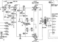
I think that something is wrong in the schematic. The gridleak (1M) of the split load phase inverter is connected close to ground potential and the cathode level is at 110V. 
I suppose the gridleak should be connected to the junction between the 220R and 27k resistors in the cathode path of the split load.
Jan E
I suppose the gridleak should be connected to the junction between the 220R and 27k resistors in the cathode path of the split load.
Jan E
Yes, that appears to be a "typo". That 1M resistor to the grid of the phase splitter should be connected to the junction of the 220 ohm and 27K ohm resistors. I have a different (harder to read) copy of the schematic (a "factory"copy, not a Sams) and it shows that resistor going to that junction.
I've attached a copy of that one... the resistor values are hard to read (the ones on the Sams copy seem to be correct values), but the circuit layout is correct...
Regards,
Gordon.
I've attached a copy of that one... the resistor values are hard to read (the ones on the Sams copy seem to be correct values), but the circuit layout is correct...
Regards,
Gordon.
Attachments
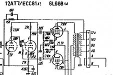
I suppose you can use standard feedback equations for the positive feedback: A'=A/(1-AB), where A=open loop gain and B=feedback fraction.
A rough estimate: Since the load (220k) in the first stage is much higher than the plate resistance the gain is not far away from mu of the tube and the gain of the split load is close to unity. This estimate gives an open loop gain (A) of let's say 40x.
The feedback fraction (B) is given by the voltage divider of the 27k and 470R resistor = 0.017.
If we put these values into the feedback equation the gain with feedback will be something like: 40/(1-0.017*40) = 125x or +10dB.
Just my 0.2dB,
Jan E Veiset
- Status
- This old topic is closed. If you want to reopen this topic, contact a moderator using the "Report Post" button.