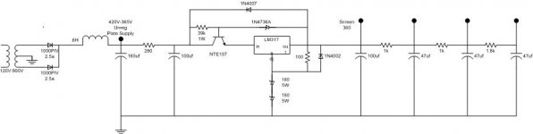
I am building a regulated screen supply using a Maida type regulator. I am trying to use 2 180V zeners to lift the adjust pin of the LM317. The zeners burn out....
The output of the regulator is connected to a 100uf Cap for the screen and 3 RC sections to feed three low current stages.
I want to get 360 for screen, 340, 330, 320 for the remaining stages. The RC sections have 47uf 450V caps.
Is it a mistake to try to do this?
The output of the regulator is connected to a 100uf Cap for the screen and 3 RC sections to feed three low current stages.
I want to get 360 for screen, 340, 330, 320 for the remaining stages. The RC sections have 47uf 450V caps.
Is it a mistake to try to do this?
How much current are you running those zeners at? If you run with a 120 ohm resistor between ref and out you will have a reference string current of 10mA which with 180V zeners means each must dissipate 1.8W - so you should be using well ventilated 5W zeners as a minimum.
One alternative would be to reduce the reference current to 1-2mA which will allow the use of commonly available 1W zener diodes. You can also use more lower voltage zeners in series to reduce individual dissipations if desired.
Make sure that all caps on the output have a discharge path through something other than the LM317 when power is removed from its input. Usually diodes back to the input supply are best for this.
Avoid the temptation to use very large caps on the output as they look like shorts during initial application of power - be sure that the pass transistor you use can handle the full supply voltage (and current) under any circumstance. Limit inrush currents..
Use a varistor across the transformer primary to protect against line borne transients.
I don't much care for the maida, summer thunderstorms or tube failures here killed every one I ever built. (long ago) In fact I don't like low voltage ss regulator chips floating on HV at all. YMMV and others here do seem to like them.
ELI and SY may have some tips on higher voltage chips that work well..
Kevin and I have had startlingly similar experiences and conclusions, but this is one place we diverge. I've never lost a Maida regulator to anything other than stupidity and carelessness. One important note though: tube guys tend to get a bit careless about heatsinking, and the stand-off pass transistor may need to dissipate quite a bit of heat.
But I'm somewhat confused by your mention of Zeners. A Maida reg uses a resistor string to set the voltage. The version I use for the Red Light District amplifier would be quite suitable for what you want to do. I've built about a dozen of them, they're all in daily service for 1-2 years, and zero failures.
But I'm somewhat confused by your mention of Zeners. A Maida reg uses a resistor string to set the voltage. The version I use for the Red Light District amplifier would be quite suitable for what you want to do. I've built about a dozen of them, they're all in daily service for 1-2 years, and zero failures.
Is this for the screens of an output stage? If so, you don't have to futz around much with bypassing the reference voltage.
A few minor suggestions. I will usually put a stopper resistor between the pass transistor and the 317; sometimes 317s will oscillate if the input isn't either bypassed or a stopper put in. 100 ohms will do, and I think that's the value that Maida used. I don't know the ratings of the 1N4736, but if it's 12-15V, you're in gravy; if it's the 6.2V I've seen in a few published designs, you're skirting danger. It's usually a good idea to snub the output cap; a 4-6 ohms will work fine. And Kevin's point is well-taken about idle current. I wouldn't go below 5mA, but the over-10 mA you have is more than needed.
A few minor suggestions. I will usually put a stopper resistor between the pass transistor and the 317; sometimes 317s will oscillate if the input isn't either bypassed or a stopper put in. 100 ohms will do, and I think that's the value that Maida used. I don't know the ratings of the 1N4736, but if it's 12-15V, you're in gravy; if it's the 6.2V I've seen in a few published designs, you're skirting danger. It's usually a good idea to snub the output cap; a 4-6 ohms will work fine. And Kevin's point is well-taken about idle current. I wouldn't go below 5mA, but the over-10 mA you have is more than needed.
SY,
Yes, primarily it is for the screens of an output stage, but the other three are for two 12ax7 amp stages and a 12au7 concertina splitter.
I will try both you and kevins suggestions. I think the idle current was causing the zeners to overheat. So I could change the ref resistor to 200 and use 7x51v zeners that should run quite cool.
How about heatsinks? I figure the drop in the pass transistor is max 50V @ around 60ma, that is just three watts.
AV
kevinkr said:I don't much care for the maida, summer thunderstorms or tube failures here killed every one I ever built. (long ago) In fact I don't like low voltage ss regulator chips floating on HV at all. YMMV and others here do seem to like them.
ELI and SY may have some tips on higher voltage chips that work well..
No reliability problems with Maida. Many in service. Mosfet version.
The more the current drawn the more the voltage difference between Maida input and output is needed for best regulation and immunity to mains born transients. Good heat sink for the IRF840 must be employed.
salas said:
The more the current drawn the more the voltage difference between Maida input and output is needed for best regulation and immunity to mains born transients.
I don't quite understand. Are you talking about current in the reference resistor or through the whole regulator? What do you mean with higher voltage difference? Eg: regulating from 450 to 360 instead of 390 to 360?
AV
avincenty said:
I don't quite understand. Are you talking about current in the reference resistor or through the whole regulator? What do you mean with higher voltage difference? Eg: regulating from 450 to 360 instead of 390 to 360?
AV
-Current through the whole reg.
-Eg: 450 to 360. Correct.
The regulator you have drawn is like the LastPAS which was in Audio Amateur in 1981 and 1982 -- without the fussy bypassing. Putting a 2W in series with the collector of the pass transistor will make the job a little easier for the little critter.
The LM317 is the source for the zener string, and the 100R resistor sets the current at about 12mA. If you are using 180V zeners they have to dissipate over 2W each, so you need 5W zeners. Better to use more zeners than one high wattage variety.
There was a correction (maybe a couple of them) to the article. I can hardly wait for Ed to come out with the 1980 issues on CD-ROM.
Since the Maida reg. is being discussed, here is a quick question for all that might know the answer (but especially SY).
The regulator will be used for driving the screens on an EL84 SE amp with LED biasing (copying Mas Penk's RH84, in effect). I will probably use two regulators. It looks (from my inexpert datasheet reading) as though the current drawn from the regulators will be of the order of 5-10mA per tube, so that's 5-10mA per regulator.
When using SY's version of the Maida, what is the lowest voltage difference that can be sustained? I ask as I suspect that the B+ of my amp will be a fair bit lower than that of SY's red light district (about 300V instead of 330V - but I haven't managed to get the power transformer measured with a decent multimeter yet).
Many thanks in advance,
James
jackinnj said:Putting a 2W in series with the collector of the pass transistor will make the job a little easier for the little critter.
How large should this 2W resistor be? I have seen this in other schematics, but wouldn't it lower the input Voltage to the regulator? Would I be better off removing the first RC section with 260 ohms and 100uf cap and put the 260 in series with the collector? Input ripple would be larger. LM317 should clean up this ripple, right?
AV
avincenty said:
How large should this 2W resistor be? I have seen this in other schematics, but wouldn't it lower the input Voltage to the regulator?
Either the regulator or the resistor is going to dissipate the un-needed voltage as "work" -- there's less stress on the regulator if some of the "work" is done by a resistor.
You can work it out backwards from the supply voltage under load.
Thanks Jackinnjjackinnj said:
Either the regulator or the resistor is going to dissipate the un-needed voltage as "work" -- there's less stress on the regulator if some of the "work" is done by a resistor.
You can work it out backwards from the supply voltage under load.
Understood. I kind of did this with the RC filter before the regulator. I used PSU designer to estimate the voltage swing under idle to max load and selected the R as to have a voltage a little greater that 360 at full load.
- Status
- This old topic is closed. If you want to reopen this topic, contact a moderator using the "Report Post" button.
- Home
- Amplifiers
- Tubes / Valves
- Maida for Screen Supply