Hi,
I just bought an Roberts (Akai) reel/reel which contains a good condition amp. After checking some of the threads here I see that rebuilding an old amp is a good way to start tube diy. I would like to go SE and have a couple questions. The amp came with the following:
2 6BM6
2 12AT7
1 6CA4
The only reference I could find on this amp discribed a rebuild but using 6BQ5s/ 12AD7s. Duncans doesnt show these as equivelent so want show I do? I found a schematic for a 6BM6 amp but Im not sure its really hifi. Any suggestion as to where to start. I would like to stay SE triode if possible (flea power is fine)
Thanks amt
Attachments
Did you try them out as is?
Hi
If this is the Akai M-8/Roberts 770X, then the two EL84 amplifiers in there are perfectly servicable as-is. They are actually pretty good monoblock amplifiers (many 'audiophile's have been alarmed to find how much so) - a pretty conservative, safe design ensuring longevity and safety of tubes.
All I would recommend you do is check the PS capacitor's health and add connectors to run them properly as monoblocks, and you'd be surprised how good they sound!
I understand the DIY itch, however, and there are many other designs more worthy of your time I think. For example the JE Labs Simple 45
http://users.starpower.net/je2a3/simple45.htm, is one that I have found is quite suitable for a DIY beginner (like I once was...).
Hope this helps -
Pradeep
Pradeep,
The model is a 1630 and unfortunately, is part of a preamp and tape recorder "mess" of wiring on the chassis. The direction I wanted to go can be seen at http://rummageads.com/tstereo/SEstereoamp/
Also, I really wanted to use the parts for a cheap first project.
amt
The model is a 1630 and unfortunately, is part of a preamp and tape recorder "mess" of wiring on the chassis. The direction I wanted to go can be seen at http://rummageads.com/tstereo/SEstereoamp/
Also, I really wanted to use the parts for a cheap first project.
amt
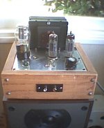
I had one of these with a blown power transformer, used it as the basis for a small SE amp. Mine had the tube lineup of 2x 6BM8 (ECL82) and 2x 12AT7. Output transformers were pretty darn good, actually, as was the ELNA power supply cap (2x 40 uF).
I would suggest completely gutting the unit (with its incrdibly dodgy wiring and leaky ceramic caps) and starting from scratch. You might also want to use a tube rectifier (I used a 5V4G for the hell of it.)
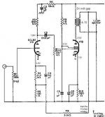
I built the Mullard schematic at Bonavolta
It actually had a really good sound, but I have somehow borked it a little
When I get around to it I will buy some of the Svetlana 6BM8 (they are still being made)
Here is a webcam pic:
I would suggest completely gutting the unit (with its incrdibly dodgy wiring and leaky ceramic caps) and starting from scratch. You might also want to use a tube rectifier (I used a 5V4G for the hell of it.)
I built the Mullard schematic at Bonavolta
It actually had a really good sound, but I have somehow borked it a little
When I get around to it I will buy some of the Svetlana 6BM8 (they are still being made)
Here is a webcam pic:
Attachments
shiFtY,
Thanks for the help and the schematic. That looks to be relatively simple, will require few new parts and will actually sound good too! Perfect for a first tube diy.
Ive already dismantled the amp and am not sure how it was originally assembled. I barely had room to snip the wires much less assemble and solder. The nice Elna cap looks like a beer can that was opened after being shaken. Too bad 'cause it really looked nice.
The ez81 that came w/ it tested fine so I guess I'll use it unless theres a good reason why not to use it.
My next step is to become alittle more adept at reading tube schematics so I dont fry myself or the parts.
amt
Mullard amp
While I am a big fan of Mullard circuits, the one reservation I have with this ECL82 amp is that the balance control is within the feedback loop, and thus feedback levels will alter with the setting of this control. Even though the feedback level is quite small by modern standards (about 6db) it might be advisable to place the balance at the input of the amp, possibly before the vol/tone control network.
While I am a big fan of Mullard circuits, the one reservation I have with this ECL82 amp is that the balance control is within the feedback loop, and thus feedback levels will alter with the setting of this control. Even though the feedback level is quite small by modern standards (about 6db) it might be advisable to place the balance at the input of the amp, possibly before the vol/tone control network.
Another Mullard...
Me to!!!
Good remark ...i'm with you a second time!
And why not take out the balance all together...i never use it...and it compromise the sound quality...
also the tone control if was me will be deleted...(i'm a purist)
Last sugestion...this amp has been designed in the good old days of AM radio and ceramics and piezo cristals pic ups ...so the high frequency demands are not so great as today...and the input 1 MOhm volume resistor in conjunction with the Miller capacitance of the first stage will atenuatte to much the high frequencys...so i sugest to change the pot to a 100K log pot...
While I am a big fan of Mullard circuits
Me to!!!
the one reservation I have with this ECL82 amp is that the balance control is within the feedback loop, and thus feedback levels will alter with the setting of this control
Good remark ...i'm with you a second time!
it might be advisable to place the balance at the input of the amp, possibly before the vol/tone control network
And why not take out the balance all together...i never use it...and it compromise the sound quality...
also the tone control if was me will be deleted...(i'm a purist)
Last sugestion...this amp has been designed in the good old days of AM radio and ceramics and piezo cristals pic ups ...so the high frequency demands are not so great as today...and the input 1 MOhm volume resistor in conjunction with the Miller capacitance of the first stage will atenuatte to much the high frequencys...so i sugest to change the pot to a 100K log pot...
Mullard amp
....I also think that if the input impedence is reduced for modern sound sources rather than for medium output ceramic cartridges, the total gain will not be required either, and perhaps the level of feedback could be increased. As it stands, this circuit has quite high levels of distortion at full output (5% at 2W) so any method to help reduce this would be welcome....
....I also think that if the input impedence is reduced for modern sound sources rather than for medium output ceramic cartridges, the total gain will not be required either, and perhaps the level of feedback could be increased. As it stands, this circuit has quite high levels of distortion at full output (5% at 2W) so any method to help reduce this would be welcome....
Sentimental reasons...
I think that for us Europeans the Mullard is the some that the Dyna ST 70 from ours friends in the States...the same sentimental reasons...and the some memories of the days when the audio was young...
Yes another good idea...now the gain is 34 X ...considering the output power...tha gain can be reduced to half that value...with the consequent halving in distortion....noise...and doubling the damping factor!
Thats the fun of diyaudio...
I think that for us Europeans the Mullard is the some that the Dyna ST 70 from ours friends in the States...the same sentimental reasons...and the some memories of the days when the audio was young...
the total gain will not be required either, and perhaps the level of feedback could be increased.
Yes another good idea...now the gain is 34 X ...considering the output power...tha gain can be reduced to half that value...with the consequent halving in distortion....noise...and doubling the damping factor!
Thats the fun of diyaudio...
So you're saying...
to eliminate RV1 (1M log), eliminate RV7 (500k log) and replace RV2 with a 100k log pot. Sorry but Im still in my circuit reading infancy. This is referenced to shiFtYs schematic link. Im also not clear as to where the tone controls are.
BTW, I used to own a ST70 and a PAT3 but sold them to buy "high power" SS stuff. Wish I still had them now since Ive gotten wise to higher efficiency speakers and all my old SS stuff is close to worthless. Oh well.
amt
to eliminate RV1 (1M log),
No...change RV1 for a 100K log pot...this is the volume control pot!
And conect the wiper (midle pin) to the grid of the input valve...
eliminate RV7 (500k log)
Yes!...put a 470 K resistor in this place!
replace RV2 with a 100k log pot.
No ...delete RV2 and C1....if you don´t need tone controls...
Regards.
PS: pay atention at charged capacitors and high voltage...sorry but i don´t know your knowledge...
Sorry i forgot...the tone control is RV2...and yes is the circuit in shiFtYs schematic link!
Does the wire between the tube still remain in place
Yes i think that you talk about the conection betwen the resistor and the output tube grid...
which side of the resistor does it connect?
The side of the resistor oposite to ground... where the resistor conect to C3...
Fell free to ask...i hope that i know how to answer...heheheheh(last question I think?)
Be my guest... motorcycle friend
Also one thing I found is that the negative feedback resistor (R9) is quite variable: you can leave it out all together if you wish. I found around 10K sounded good (a tiny amount). You can play around here- but don't go too low (I didn't go below 5K)
The Akai output transformers have only the 8ohm winding for speakers, so you have to take it from there. (Many other transformers have taps for 4, 8, 16 ohm)
Also another tip- when you first fire it up, use the crappy akai speakers for testing purposes, in case you have made a mistake.
Oh, and also never run a valve amp without speakers Fireworks result. 
Make sure you keep us posted!
The Akai output transformers have only the 8ohm winding for speakers, so you have to take it from there. (Many other transformers have taps for 4, 8, 16 ohm)
Also another tip- when you first fire it up, use the crappy akai speakers for testing purposes, in case you have made a mistake.
Oh, and also never run a valve amp without speakers
Fireworks result. Make sure you keep us posted!
ShiFtY said:Also one thing I found is that the negative feedback resistor (R9) is quite variable: you can leave it out all together if you wish. I found around 10K sounded good (a tiny amount). You can play around here- but don't go too low (I didn't go below 5K)
The Akai output transformers have only the 8ohm winding for speakers, so you have to take it from there.
The original Mullard had a feedback resistor of 3.3k from a 4 ohm winding, so from 8 ohm output it should be 6.6k to keep the original 6db feedback ratio, but if gain is not a problem you could probably reduce this resistor to well below 5k.
I have 2 Roberts branded 6BM8 R-R amps. The 2 12AT7s are part of the pre-amp circuit and aren't required.
I also have a little Calrad 6BM8 SE... it is quite a nice little amp (even stock and in need of attention).
The circuit posted was the one i was going to leverage for my units -- the designer is no slouch. The Japanese are quite enamoured of the 6BM8 -- you can probably find some more references.
dave
planet10 said:The Japanese are quite enamoured of the 6BM8 -- you can probably find some more references.
dave
The 6BM8/ECL82 was quite popular here in the UK as well, especially for portable grams in the early 1960s. They are still used today - this link shows a pdf of a kit amp which looks loosely based on the Mullard stereo 7w per channel design, but without the 1/2 ECC83 for each channel.
http://www.worldaudiodesign2.co.uk/pdf/kecl82.pdf
- Status
- This old topic is closed. If you want to reopen this topic, contact a moderator using the "Report Post" button.
- Home
- Amplifiers
- Tubes / Valves
- What to build w/ Akai parts?