Old Tube Radio - Restauration Project
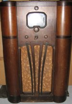
Look what me and my wife we bought at a garage sale this past weekend. We got it for just the price of the wood furniture that just need a little work to look gorgeous. My wife likes to restore old furniture, her father use to build wood furniture, so it runs in the family.
The guy said the radio was working but couldn't make it work really. He said it is from 1936. His dad was the original owner. It was only making background noise. But at least it was telling me that the supply, audio amplifier and full range speaker were probably Ok.
It is an AM, Short wave receiver all tube. Using a 5Y3 rectifier supply. All tube filaments lights up. The dial indicator window is just perfect, as well the multi-turn rope dialing mechanism. The control knobs are in wood The gold fabric covering the speaker is also perfect.
Model: Rogers Majestic 7B 732, S/N: A5288
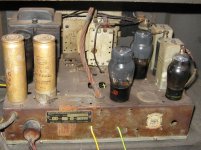
Tubes complement:
5Y3 - Rectifier + 2 X 12uF, 500V caps
6F6C (2X): Beam Pentode (Audio Amp I guest)
Radio section:
6A7M: PentaGrid Converter
6K7M: Triple-Grid Super-Control Amplifier
6B6G: Dual-Diode Triode (Possibly modulation detector)
and a nice Tuning-Eye 6X6
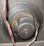
It has a very nice full range, high efficiency. speaker.
I would like to restore it, and install it in my listening room. I can always use my HP8640 RF generator to modulate in AM feeds by my computer and iTune music
Problem may well be only corroded tube socket, out-of-value carbon resistor, drifted capacitor.
Any help, typical schematic, etc from experience radio guru would be appreciated
Look what me and my wife we bought at a garage sale this past weekend. We got it for just the price of the wood furniture that just need a little work to look gorgeous. My wife likes to restore old furniture, her father use to build wood furniture, so it runs in the family.
The guy said the radio was working but couldn't make it work really. He said it is from 1936. His dad was the original owner. It was only making background noise. But at least it was telling me that the supply, audio amplifier and full range speaker were probably Ok.
It is an AM, Short wave receiver all tube. Using a 5Y3 rectifier supply. All tube filaments lights up. The dial indicator window is just perfect, as well the multi-turn rope dialing mechanism. The control knobs are in wood
The gold fabric covering the speaker is also perfect.Model: Rogers Majestic 7B 732, S/N: A5288
Tubes complement:
5Y3 - Rectifier + 2 X 12uF, 500V caps
6F6C (2X): Beam Pentode (Audio Amp I guest)
Radio section:
6A7M: PentaGrid Converter
6K7M: Triple-Grid Super-Control Amplifier
6B6G: Dual-Diode Triode (Possibly modulation detector)
and a nice Tuning-Eye 6X6
It has a very nice full range, high efficiency. speaker.
I would like to restore it, and install it in my listening room. I can always use my HP8640 RF generator to modulate in AM feeds by my computer and iTune music
Problem may well be only corroded tube socket, out-of-value carbon resistor, drifted capacitor.
Any help, typical schematic, etc from experience radio guru would be appreciated
Attachments
It's really very nice. What a prize! I have an RCA Victrola from 1946 that I am very proud of so I understand your joy.
I looked a bit on Nostalgia Air trying to find a schematic for you but was unsuccessful. You might sped a little time there in case you find something that seems like it may be a match or something that's pretty close to your set.
http://www.nostalgiaair.org/Resources/485/T0000485.htm
I'm no guru, but I have been servicing and repairing valve type audio gear for some 30+ years and I can tell you that in a set of that age you need to check every component. I expect you are right, however, that the old capacitors (condensers?) and carbon resistors are no where close to original specification. One of the many virtues of valve equipment is that very often they will still function reasonably well with components that are out of spec, although less so with RF circuits.
I wish you well with your new project!
Best regards,
Wade
Ah! Tube Radios
The most problematic thing on old radios, that have set for a long time (Besides the OLD WET style of Electrolytic Capacitors drying out) is that the mica capacitors in the IF Transformers like to get brittle and the plates of the capacitors, inside the IF Cans like to short .
Thus the tuned circuit of the IF Can is no nonger a tuned circuit.
The Primary Winding of the IF Can is wired in a series between the B+ and the Plate of the IF Amplifier Tube.
The Secondary Winding of the IF Transformer feeds the Grid of the following Tube and its bottm part of the winding is often receiving an AGC Gain Control Voltage from the AM Detector Tube Ckt.
Also, the Tuning Capacitor in the Front end will often grow crud between its meshing plates which will short out the Local Oscillator tuned Ckt and the Loop Antenna winding (AM Band).
It appears that the Speaker is an Electro Magnet type of loudspeaker (?) .
That type of speaker passes the output of the Power Supply's lightly filtered DC through the Electromagnet Coil (not the voice coil) and uses it as part of a Filter Choke for the Power Supply.
Whatever hum was unable to be filtered out, is reverse phased by passing the lightly filtered dc through the Electro magnet on the speaker and thus canceling the hum in the audio output ckt of the radio---a neat approach!
This method requires no brute force filtering of the Power Supply to yield a hum free (almost) audio.
I'll check and see if I still have my manual of OLD ! Radio Schematics --if so I'll send you a copy of the schematic that matches your radio, or comes close to matching it.
Good Luck with the restore!
Gorgeous radio!
Restoring old radios was what got me into Tubes, which trigged my interest in DIY audio, so I advise you to be careful, one moment I was looking through my grandparent's basement and stumbled upon an old radio, two years later, I am currently finishing a pair of full-range bi-pole speakers (its a slippery slope, good sir)
I have never found a radio that required anything beyond a Re-cap (i'm lucky) but
I ask you to not give up, because you will eventually get this hunk of junk to work with enough work (and without too much money), you'll be amazed by the sound quality and you will have total licenses to use the term "they don't make 'em like they used to"
I have a WWII era shortwave radio i need to re-cap, and you might have just given me the inspiration to jump back into this amazing hobby.
-Moose
by the way, NEVER EVER touch the chassis of the radio while it is on!!! this includes using the tuning/volume dials without the knobs!!! I made that mistake once, i should be dead.
Your radio is a nice one. There have been a few changes made to it I'm sure, not the least of which is the rectifier stage. Those sets used a pair of 2X3 rectifier tubes. These tubes were peculiar to the Rogers/Rogers Majestic/DeForest Crosley radios made in Canada. They were commonly removed as a pair and replaced with one 5Y3 or similar. The other rare tube in your set, and you should hope, possibly pray that it is in good working order, is the 6X6 eye tube. They are for the most part unavailable and when a good used one goes for auction, they can fetch upwards of $100. Fortunately, they can be replaced with a Russian made 6E5GT (octal) and this replacement doesn't require much modification. There should only be one 6F6 audio tube in your set, so if you find two, you may want to do a bit of preventative troubleshooting and checking before you plug it in.
Safety .... it's always good to be safe, but ... you can't get a shock just by touching the chassis, you need to create a path for the current, so try not to touch a power source with one body part and then ground yourself with another body part. This is a transformer set, so the only way you're going to get AC household power onto the chassis is via a defective component - once again, do a bit of common sense checking before you power up
I will scan the service manual for you this weekend - I have the one for the 7D732 which is the DeForest Crosley equivalent and uses the same chassis.
cheers for now
Edit :: one more thing ... you'll find when you remove the speaker to check it out, that it's actually quite small. Most of it is a steel dish that it mounts onto. The steel dish is about 12" diameter and that is what screws to the soundboard.
Thanks a lot guys fro all this useful informations. John I'll wait for the scan documentation. Indeed the 6X6 is in perfect working order, one of the first thing I checked. Intensity is also high.
I knew it would make an interesting project
This thing about the electromagnet speaker used as part of the power supply filtering, I didn't know. Nice trick indeed.
By the way I paid 100$ for it. I taught it was a very fair price. One of the two dial light is still operational. I can get a replacement one easily for the other one.
Any suggestion for the furniture cabinet restoration? My wife was expecting to remove the old, scratched varnish, then put some new one. We will match the different colors. We will keep the central section where the dial window is intact because it has the frequency bands switch lettering on it and some nice wood finish.
Naturally, I'll remove all electronics from the frame before proceeding.
Any danger to damage the dial lettering if using varnish remover fluid on the other parts of the frame, maybe because of the chemical vapors?
Well, I guess congratulations are in order - a nice set for about 1/2 of what it should go for and a free, working 6X6 eye tube to boot - ya' did good eh!!
Here's a link to the service manual:
Service manual pages - Majestic 7M732
cheers eh?
ps : the finish is toned lacquer - the cabinet is not stained, as far as I know just the lacquer is toned - you "might" be able to repair the scratches by reflowing the lacquer with lacquer thinners instead of stripping, masking and respraying.
mikecj said:The "eye" tube I had downstairs was a 6C5 not 6x6 sorry
Anyone have a use for it let me know.
Do you mean 6E5?
- Status
- This old topic is closed. If you want to reopen this topic, contact a moderator using the "Report Post" button.
- Home
- Amplifiers
- Tubes / Valves
- Old Tube Radio - Restoration Project