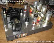
I have completed to make an E-Linear Amp based on Pete's design with my modification.
The sonic is very vivid. I have never heard such a atmosphere made by the amp.
I have up-loaded the measured results into my Web as below (sorry in Japanese) .
http://ja1cty.servehttp.com/E-LINEAR/
Many thanks to Pete to give me good suggestions.
The sonic is very vivid. I have never heard such a atmosphere made by the amp.
I have up-loaded the measured results into my Web as below (sorry in Japanese) .
http://ja1cty.servehttp.com/E-LINEAR/
Many thanks to Pete to give me good suggestions.
Attachments
Hi ja2dhc,
thanks for posting the schematic.
http://ja1cty.servehttp.com/E-LINEAR/E-Linear-amp.jpg
You should make the C3g anode floating on the cathode signal
like it is done in e.g. Loftin White.
Kind regards,
Darius
thanks for posting the schematic.
http://ja1cty.servehttp.com/E-LINEAR/E-Linear-amp.jpg
You should make the C3g anode floating on the cathode signal
like it is done in e.g. Loftin White.
Kind regards,
Darius
Re: Re: Pete's SE E-Linear
I cannot understand your point. What is the benefit ?
oldeurope said:You should make the C3g anode floating on the cathode signal
like it is done in e.g. Loftin White.
I cannot understand your point. What is the benefit ?
Re: Re: Re: Pete's SE E-Linear
Hello ja2dhc,
have a look at the upper 70µF . Signal voltage drop at this cap causes
a signal voltage drop at the 500R resistor (cathode EL34).
This drop is deducted from the grid-cathode signal voltage.
Look how Loftin White solved this "problem".
The drive signal voltage for the power tube floates on the cathode
potential of the power tube. Very clever, isn't it?
Kind regards,
Darius
PS: In the WE (repeater amp) they made the secondary of the input transformer floating.
ja2dhc said:
I cannot understand your point. What is the benefit ?
Hello ja2dhc,
have a look at the upper 70µF . Signal voltage drop at this cap causes
a signal voltage drop at the 500R resistor (cathode EL34).
This drop is deducted from the grid-cathode signal voltage.
Look how Loftin White solved this "problem".
The drive signal voltage for the power tube floates on the cathode
potential of the power tube. Very clever, isn't it?
Kind regards,
Darius
PS: In the WE (repeater amp) they made the secondary of the input transformer floating.
Hi Darius,oldeurope said:Hello ja2dhc,
thanks, I am happy to help you.
Best wishes,
Darius")
I found this thread on my search for a C3g application. I want to use this tube as a driver in a 2A3-amp. The circuit could be quite similar to the one ja2dhc uses.
You recommend to "make the C3g anode floating on the cathode signal".
I had a look at your very interesting website but I must confess, that I did not understand everything immediately.
If we stay with the given supply voltages and RC-coupling between driver and power stage, how would the practical approach look like in the circuit ja2dhc shared with us?
regards
pieroh
Hi Darius,
Nice concepts. There is something pleasing about the idea of direct coupling. Your blogs are interesting; makes me wish I had kept up with my German. One question: You mention the lack of cathode decoupling capacitors, but isn't C2 still a cathode decoupling capacitor?
Sheldon
Nice concepts. There is something pleasing about the idea of direct coupling. Your blogs are interesting; makes me wish I had kept up with my German. One question: You mention the lack of cathode decoupling capacitors, but isn't C2 still a cathode decoupling capacitor?
Sheldon
Chb
Hello pieroh,
A practical approach is given by Loftin White.
Chb makes the driving signal floating on the cathode of the output triode.
This is one of the unknown secrets in the Loftin White topology.
Kind regards,
Darius
Originally #7 posted by pieroh
Hi Darius,
... The circuit could be quite similar to the one ja2dhc uses.
You recommend to "make the C3g anode floating on the cathode signal".
I had a look at your very interesting website but I must confess, that I did not understand everything immediately.
If we stay with the given supply voltages and RC-coupling between driver and power stage, how would the practical approach look like in the circuit ja2dhc shared with us?
regards
pieroh
Hello pieroh,
A practical approach is given by Loftin White.
Chb makes the driving signal floating on the cathode of the output triode.
This is one of the unknown secrets in the Loftin White topology.
Kind regards,
Darius
C2 and Chb
Hello Sheldon,
cathode cap to ground is forbidden in a Loftin White.
If you make a bypass capacitor parallel the cathode resistor,
Chb will not be able to eliminate the losses of C2.
Kind regards,
Darius
Originally #8 posted by Sheldon
Hi Darius,
... One question: You mention the lack of cathode decoupling capacitors, but isn't C2 still a cathode decoupling capacitor?
Sheldon
Hello Sheldon,
cathode cap to ground is forbidden in a Loftin White.
If you make a bypass capacitor parallel the cathode resistor,
Chb will not be able to eliminate the losses of C2.
Kind regards,
Darius
Re: Chb
My E-Linear amplifier does not use the by-pass capacitor for
EL-34B cathod resister, as is shown below.
http://ja1cty.servehttp.com/E-LINEAR/E-Linear-amp.jpg
It is following to the origilal E-Linear Amplifier by Pete Millett.
His article is indicated below.
http://www.pmillett.com/elinear.htm
My E-Linear amplifier does not use the by-pass capacitor for
EL-34B cathod resister, as is shown below.
http://ja1cty.servehttp.com/E-LINEAR/E-Linear-amp.jpg
It is following to the origilal E-Linear Amplifier by Pete Millett.
His article is indicated below.
http://www.pmillett.com/elinear.htm
Re: C2 and Chb
OK, thinking about it a little more, maybe (or maybe not) I'm beginning to understand. If the amp is operated from an ordinary low impedance power supply, then decoupling the cathode resistor to ground or to B+ is essentially the same. The only difference is that power supply noise is injected out of phase to the output, with the B+ connection. With the inductor preceding the cap to cathode, however, that point is fed by essentially a constant current (high impedance). In that case, the cap keeps the voltage across the tube constant, instead of constant voltage across the cathode resistor. If I'm not way off there, my next task is to work on the meaning of that for feedback to the input tube.
Sheldon
oldeurope said:cathode cap to ground is forbidden in a Loftin White.
If you make a bypass capacitor parallel the cathode resistor,
Chb will not be able to eliminate the losses of C2.
OK, thinking about it a little more, maybe (or maybe not) I'm beginning to understand. If the amp is operated from an ordinary low impedance power supply, then decoupling the cathode resistor to ground or to B+ is essentially the same. The only difference is that power supply noise is injected out of phase to the output, with the B+ connection. With the inductor preceding the cap to cathode, however, that point is fed by essentially a constant current (high impedance). In that case, the cap keeps the voltage across the tube constant, instead of constant voltage across the cathode resistor. If I'm not way off there, my next task is to work on the meaning of that for feedback to the input tube.
Sheldon
If I have the logic right, since the output cathode resistor is not bypassed, it will create degeneration at the cathode. The AC connection to the input cathode, in essence, is a positive feedback (or regeneration?) that counters the degeneration at the output tube cathode. Looking at Darius's resistor divider, I see about 60:1, which matches the mu of about 60 for the input tube. That seems to make sense.
Those look like pretty linear tubes. Nice looking construction too. Were you happy with the sound?
Sheldon
Those look like pretty linear tubes. Nice looking construction too. Were you happy with the sound?
Sheldon
Re: Re: Chb
Hello ja2dhc,
thanks,
what does the "E" mean in E-Linear?
Kind regards,
Darius
Originally #11 posted by ja2dhc
My E-Linear amplifier does not use the by-pass capacitor for
EL-34B cathod resister, as is shown below.
http://ja1cty.servehttp.com/E-LINEAR/E-Linear-amp.jpg
It is following to the origilal E-Linear Amplifier by Pete Millett.
His article is indicated below.
http://www.pmillett.com/elinear.htm
Hello ja2dhc,
thanks,
what does the "E" mean in E-Linear?
Kind regards,
Darius
Re: Re: Re: Chb
I have no idea about it. I could not find description in the original article below, either.
http://www.pmillett.com/elinear.htm
The sonic is vivid and "High Speed." I think it is given by capacitors as below.
C3g Cathode by-pass: Wet Tantalum
Coupling: ERO 1600V rated polypropylene
OPT Cold End (70uF): Sprague polypropylene Motor Run Cap
Therefore no aluminum capacitor is used in all audio signal paths.
oldeurope said:
what does the "E" mean in E-Linear?
I have no idea about it. I could not find description in the original article below, either.
http://www.pmillett.com/elinear.htm
The sonic is vivid and "High Speed." I think it is given by capacitors as below.
C3g Cathode by-pass: Wet Tantalum
Coupling: ERO 1600V rated polypropylene
OPT Cold End (70uF): Sprague polypropylene Motor Run Cap
Therefore no aluminum capacitor is used in all audio signal paths.
- Status
- This old topic is closed. If you want to reopen this topic, contact a moderator using the "Report Post" button.
- Home
- Amplifiers
- Tubes / Valves
- Pete's SE E-Linear