I am thinking of using a 6j5 dc coupled to 12b4 as a 2a3 driver for an SE amp.
I came up with this circuit:
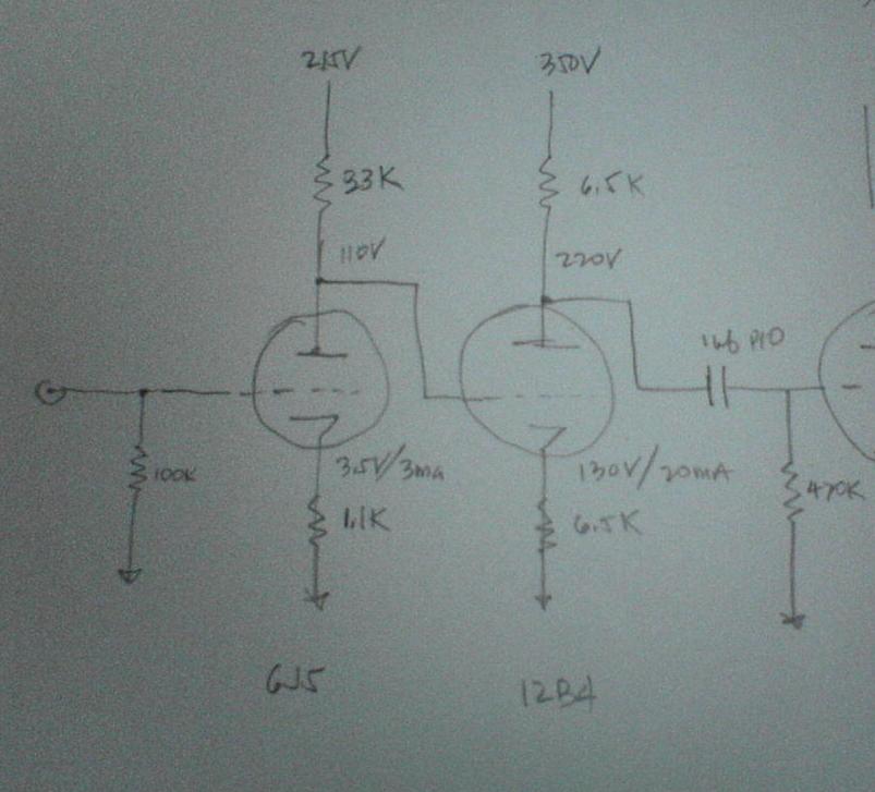
(sorry about the quality of the photo, I have a new PC at home and I have not installed the software I need to draw a decent schematic).
I forgot to draw a line from the input to ground.
This will be my first DC coupled computation, will this work? Thanks!
I came up with this circuit:
(sorry about the quality of the photo, I have a new PC at home and I have not installed the software I need to draw a decent schematic).
I forgot to draw a line from the input to ground.
This will be my first DC coupled computation, will this work? Thanks!
Don't see any problems there. I would suggest adding a grid stopper to the 12B4 to help limit any grid current during warm up. VTs are quite "forgiving" and as long as you come close to design nominal voltages, it'll work just fine.
I used the same sort of DC coupling between a first preamp and an LTP splitter with no trouble at all. You do, however, have to pay attention to Vhk ratings when doing designs like this.
I used the same sort of DC coupling between a first preamp and an LTP splitter with no trouble at all. You do, however, have to pay attention to Vhk ratings when doing designs like this.
Just a thought, I have found that both linearity and sound quality improve considerably when running the 6J5 at higher currents. I tend to run them at 8 - 10mA typically.
You will need a high quality cathode bypass cap on the 12B4 if you expect both reasonable swing and sufficient gain, otherwise you have unity gain and the 6J5 will do about as well in terms of rp with the addition of a cathode bypass or led derived cathode bias.
You will need a high quality cathode bypass cap on the 12B4 if you expect both reasonable swing and sufficient gain, otherwise you have unity gain and the 6J5 will do about as well in terms of rp with the addition of a cathode bypass or led derived cathode bias.
If the plate of the 6J5 is at 110v, then the cathode of the 12B4 will be at about 120V, so the 12B4 is operating at 100v, ~16mA. You don't show the 2A3 OP in your picture, but at usual operating points this device will have a Vg-k of about -45v. I do not think you're going to get 90v swing out of a device operating at 100v p-k. You might want to experiment with a lo-vo current source or some other lo-drop load, to get some more output swing out of your driver.
I'm not saying anything about the sound or anything, just your ability to fully modulate your output tube, which can be of practical importance in a 3w amp.
Anybody see something I'm missing?
Aloha,
Poinz
I'm not saying anything about the sound or anything, just your ability to fully modulate your output tube, which can be of practical importance in a 3w amp.
Anybody see something I'm missing?
Aloha,
Poinz
Yah, that's the problem I've been struggling with right along with 2A3 and 45 designs; the low B+ voltage, paired with the big required grid swing. The problem becomes especially acute with a two-stage direct-coupled front end. It might even be worthwhile building a separate high-volt low-amp supply for the driver stage.
Aloha,
Poinz
Aloha,
Poinz
Poindexter said:If the plate of the 6J5 is at 110v, then the cathode of the 12B4 will be at about 120V, so the 12B4 is operating at 100v, ~16mA. You don't show the 2A3 OP in your picture, but at usual operating points this device will have a Vg-k of about -45v. I do not think you're going to get 90v swing out of a device operating at 100v p-k. You might want to experiment with a lo-vo current source or some other lo-drop load, to get some more output swing out of your driver.
I'm not saying anything about the sound or anything, just your ability to fully modulate your output tube, which can be of practical importance in a 3w amp.
Anybody see something I'm missing?
Aloha,
Poinz
Poinz,
Thanks for bringing up the voltage swing issue.
I have a nice plate choke that I can use to load the 12b4, I will re-compute the 12b4 OP.
Thanks.
kevinkr said:Just a thought, I have found that both linearity and sound quality improve considerably when running the 6J5 at higher currents. I tend to run them at 8 - 10mA typically.
I disagree. Take a look at these loadlines:
[img=http://img364.imageshack.us/img364/8010/6j5loadline100kpo4.th.png]
This one has a static plate current of 1.0mA. I used this particular design in a project, and it sounds great. There is no need to be pushing so hard, especially with an up front gain stage where the output voltage swing is limited, and you don't need gobs of current to drive the Ci of the next stage. In this case, by the "Rule of Five", a static plate current of just 0.85mA would have sufficed.
Graphical THD estimates tend to run a bit high, and since this particular gain stage had an unbypassed cathode resistor, the THD in practice was a good deal lower, and all but immeasureable.
Here's another one:
http://img301.imageshack.us/img301/5610/6j5loadline60klu9.png
This runs a bit hotter, but still under 5.0mA of static plate current. I could have used this one, but at the expense of higher voltage that would exceed the Vhk of the following stage to which it was DC coupled.
You don't need big currents with this type, even though they are rated for quite a bit of plate dissipation, which would come in handy for drivers. For each type, there appears to be some "magic" plate currents where the g(m) and r(p) change at the same rate, leading to quite linear operation. For 6J5s, it would appear that under 5.0mA of static plate current hits that point.
The completed project sounds just great.
salas said:You need 130V pk-pk signal to drive the 2A3.
Actually ~90V pk - pk is my experience on a 250V supply at 60mA with any US made tube I have tried, and the Sovtek monoplate as well. Bias typically -45V to -48V fixed bias, or ~the same effective value with cathode bias. (300V supply)
Miles Prower said:
I disagree. Take a look at these loadlines:
[img=http://img364.imageshack.us/img364/8010/6j5loadline100kpo4.th.png]
This one has a static plate current of 1.0mA. I used this particular design in a project, and it sounds great. There is no need to be pushing so hard, especially with an up front gain stage where the output voltage swing is limited, and you don't need gobs of current to drive the Ci of the next stage. In this case, by the "Rule of Five", a static plate current of just 0.85mA would have sufficed.
Graphical THD estimates tend to run a bit high, and since this particular gain stage had an unbypassed cathode resistor, the THD in practice was a good deal lower, and all but immeasureable.
Here's another one:
http://img301.imageshack.us/img301/5610/6j5loadline60klu9.png
This runs a bit hotter, but still under 5.0mA of static plate current. I could have used this one, but at the expense of higher voltage that would exceed the Vhk of the following stage to which it was DC coupled.
You don't need big currents with this type, even though they are rated for quite a bit of plate dissipation, which would come in handy for drivers. For each type, there appears to be some "magic" plate currents where the g(m) and r(p) change at the same rate, leading to quite linear operation. For 6J5s, it would appear that under 5.0mA of static plate current hits that point.
The completed project sounds just great.
Hi Miles,
Not to disagree with you but your 1mA operating point runs quite counter to my experience. You are operating near the bottom of the characteristic curves where the slope is not close to constant and yet you apparently get good results. Given the current and RL I would assume that rp is quite high? Can you elaborate - and have you actually measured the thd, and what sort of HF bandwidth do you get? The thd% if true in practice is quite excellent. Like you I do have a lot of respect for the performance capability of the 6J5 and 6SN7 - I just like lots of BW and high current operation better. (There is not necessarily a rational reason for this based on your comments.) I'll probably need to try this though. Thoughts?
kevinkr said:Not to disagree with you but your 1mA operating point runs quite counter to my experience. You are operating near the bottom of the characteristic curves where the slope is not close to constant and yet you apparently get good results.
Does seem counter intuitive. Though it doesn't look very good, the 6J5 seems to be operating at a point where both the g(m) and r(p) are moving at the same rate. This is what is keeping distortion low. This is part of a system with:
6J5 -> 6SL7 (differential) -> 6SN7 (CF) -> PP 807s
The 6J5 is a low level stage, and doesn't need to swing very much: ~2.0Vp. It was necessary to add this stage since the 6SL7 diff amp alone didn't give enough gain margin for gNFB with any reasonable sort of input sensitivity. It runs with an unbypassed cathode resistor to cut the gain further, and to provide a gNFB summing node.
Given the current and RL I would assume that rp is quite high? Can you elaborate - and have you actually measured the thd, and what sort of HF bandwidth do you get?
I did a "Twin T" test on the 6J5 input stage during development to see if it really worked as well as the loadline suggested. I couldn't actually measure anything since whatever harmonics were being generated after nulling out the fundamental were buried too far under the noise. I have a very noisy QTH due to having a 50KW BCB xmtr just 30 miles to the north, and the AM gets into everything, even when working in a basement. As for BW, the -3.0db(v) f(h) was 45KHz for that stage, due to the high r(p) you get at such low plate currents.
Overall, the measured BW of the whole amp was: f(l)= 10Hz; f(h)= 29KHz (Open loop) the f(h) being limited by the OPT. (Hammonds, with advertised f(h) of 30KHz).
f(l)= ~7.0Hz; f(h)= 38KHz with 6.0db(v) of gNFB.
The thd% if true in practice is quite excellent. Like you I do have a lot of respect for the performance capability of the 6J5 and 6SN7 - I just like lots of BW and high current operation better. (There is not necessarily a rational reason for this based on your comments.) I'll probably need to try this though. Thoughts?
Working at higher static plate currents would probably be best for line stages where you need to source some current into cable capacitance. For lower level operation, it's probably not necessary. Adds some more flexability to the design when using 6SN7-oids.
Cool, Miles..
Interesting results, clearly a lot of thought went into this design.
Interesting comments on the bcb interference in your basement lab.
I have the same sort of issues (in my basement lab) when doing relatively broadband measurements - I have found doing fft based measurements can help in this regard as most of the noise is out of band and as long as it is not detected does not seem to cause much mischief - boy is it noticeable on my scope though, enough noise in fact that in many cases it swamps the noise generated by the circuit I am trying to test when looking at ripple, etc. on the output of an amp or pre-amp... (filters do help, but don't cure the issue.)
I live just outside of Boston and there are a lot of am/fm/tv transmitters in the vicinity, cordless phones don't help much either..
Hi,
I am stumbling throught this thing. This is the first time I posted anything on the web, and I'm not sure how to post a new topic.
Anyway, I typed in 12b4 tube preamp and I ended up here. Besides posting a new thread or whatever it's called, my other question is this:
Has anybody out there encountered problems with 12b4 tubes? Every one I've used has gone bad within anywhere from 2-24 hours of operation. B+ used has been anywhere from 250-300+ volts, plate resistors 5+k to 7k, Rk usually 500 ohms.
Is there a manufacturing defect with 12b4s, or am I doing something seriously wrong with the couple dozen 12b4s I have so far gone through?
I have never had problems getting other tube types to hold bias and gain as I have had with 12b4s, and since I see so many posts from builders who get the job done, I welcome any feedback on my problem.
When the 12b4 works and holds bias(instead of dropping like a rock), it's gotta be the best audio device I've heard, so I'm desperate to get a pre built and use the tube in a power amp.
Please help!
notleon said:Has anybody out there encountered problems with 12b4 tubes? Every one I've used has gone bad within anywhere from 2-24 hours of operation. B+ used has been anywhere from 250-300+ volts, plate resistors 5+k to 7k, Rk usually 500 ohms.
I built a 12b4 preamp and a 12b4 parafeed amp (using the 12b4 as power tube), I still have to ruin a 12b4.
I never have this problem.
What do you mean everything has gone bad? Check the heater voltage?
Indeed I've used 12b4s from preamp to output tubes. Nice and neutral but not very exciting. They measure all over the place but once matched and working should be OK.
6S4A tend to measure closer together - they work as drivers, output tubes etc. I've had them as output tubes in PPP for years with no problems. Slightly higher Rp. Cheap as chips.
Andy
6S4A tend to measure closer together - they work as drivers, output tubes etc. I've had them as output tubes in PPP for years with no problems. Slightly higher Rp. Cheap as chips.
Andy
Overall, a nice clean topology, and as Kevin(KR) mentioned... a bypass cap on the driver at minimum. I would suggest dropping the 2A3 grid resistor from 470K to no more than 250K. I know the spec. states 500K, but that's asking for trouble... especially as the tube ages.
I did a similar engineering project for a 45/2A3 SET design a couple years back... spent about 9 months (part time) on it. I tried quite a few tubes in the input/driver stage and actually settled on a 5814A. It proved to be the best for low distortion, wide bandwidth and low noise and easily handles the cathode to filament voltage for the driver stage. It has about 43dB of gain, can cleanly swing 120 volts peak-to-peak and results in a bandwidth that is within 1dB at 40KHz.
I used standard formulas to calculate driver current to realize the proper slew rate and output voltage against the input capacitance of the output tube. More (current) never hurts of course, but more akin to using a larger hammer to flatten a fly... end result, still flat.
I would also recommend tailoring your low frequency points via bypass and coupling caps. Coupling to below 1Hz sounds good on paper, but with source material you can get some interesting problems... like vinyl warps that will swamp your output stage and either saturate the core or drop it out on the opposite (signal) swing. Rumble can do the same and digital isn't perfect in this regard either. I tailored my design to be 1dB down at 25Hz. Note: one exception, do bypass the driver cathode below 1Hz.
Do post some more once you get an initial prototype running.
Regards, KM
andyjevans said:Indeed I've used 12b4s from preamp to output tubes. Nice and neutral but not very exciting. They measure all over the place but once matched and working should be OK.
6S4A tend to measure closer together - they work as drivers, output tubes etc. I've had them as output tubes in PPP for years with no problems. Slightly higher Rp. Cheap as chips.
Andy
I built a EF86 driven 6s4a parafeed amp, and now it plays as my main amp driving a pair of Fostex 167e. For me, it sounds a bit better than my 6n1p driven KT88 SE amp.
I am in the planning stage for a 2a3 parafeed amp, am thinking of using a pair of 6s4a to drive it, might not have enough swing, but I want to try anyway.
alexg said:
I built a EF86 driven 6s4a parafeed amp, and now it plays as my main amp driving a pair of Fostex 167e. For me, it sounds a bit better than my 6n1p driven KT88 SE amp.
I am in the planning stage for a 2a3 parafeed amp, am thinking of using a pair of 6s4a to drive it, might not have enough swing, but I want to try anyway.
Funny you should say this - I was just building a PP2a3 amp with 6S4A drivers, because I too use 6S4A outputs in my main amp. Unfortunately I ran out of space and have substituted a ECC99 as driver. I wanted to transformer couple to the 2a3s with a LL1660 but again, no space so it will have to be cap coupled. I'm going to try using a 1J6G as input tube. It's a nice neutral sounding small DHT. I suspect this should sound pretty good. Should know in a few days.
Andy
- Status
- This old topic is closed. If you want to reopen this topic, contact a moderator using the "Report Post" button.
- Home
- Amplifiers
- Tubes / Valves
- 6j5 dc coupled to 12b4a as 2a3 driver