Hi all,
I am upgrading a Pas 3 piece by piece, I built a LM317 regulated filament PS and it works fine no hum or hiss.
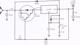
I built a LM317 + MOS HV power supply with a schematics from this site
Similar to others on this site.
The problem is quite strong Hiss on the mid-ranges and tweeters, with 0 volume , quite strong from listening distance.
I cannot see anything with a scope, just a 30 mV noise.
I made a few changes:
R5 = 240 ohm
R7 = 61k for V=320 Volts
R8 = 100
C5 = 22nF
R4 = 0
R1 = 0
What do you think ?
Should I try a P filter before C3 ? Which values ?
Rollo
I am upgrading a Pas 3 piece by piece, I built a LM317 regulated filament PS and it works fine no hum or hiss.
I built a LM317 + MOS HV power supply with a schematics from this site
Similar to others on this site.
The problem is quite strong Hiss on the mid-ranges and tweeters, with 0 volume , quite strong from listening distance.
I cannot see anything with a scope, just a 30 mV noise.
I made a few changes:
R5 = 240 ohm
R7 = 61k for V=320 Volts
R8 = 100
C5 = 22nF
R4 = 0
R1 = 0
What do you think ?
Should I try a P filter before C3 ? Which values ?
Rollo
>>I think your regulator may be oscillating. What's the value of the output cap? Are you using a gate-stopper resistor for the MOSFET? Is it positioned right at the gate?<<
Yes oscillating, but how can I see it on a scope (100MHZ analog storage TEk) ?
there is a 470ohm gate stopper at 12 mm 1/2" from gate of IRF820.
the big cap is 330uF 450V 105º after 2 Hi Volt diodes from original trafo (I use only HiV section of trafo, I added a new toroid trafo for filament),
at the output I put a filter 100ohm + 223 (=22nanoF ?) between B+ and GND.
If I check with original PS which has a ? filter after Diodes of 20uF+10Kohm+20uF+10Kohm+30uF the Hiss is bearable, I wanted to cancel it with new PS.
Attachments
Hey, that's my Maida circuit. You could also ask the author for help...
However, check that output "filter" you made, it seems suspect to me. How have you come to those values (100ohm + 22nF)? That should only be a suitable capacitor (say from 100nF to 1uF) with a small (1ohm-10ohm) resistor in series to avoid oscillations in the LM317 because of too low phase margin.
What did you connect after the regulator? If you put big, low esr capacitors from B+ to ground, they can made the LM317 oscillate.
Check your layout also, for too long wires, wires running parallel, grounding, etc etc...
Have you tried bypassing the regulator (using a power resistor to imitate it's voltage drop)? Maybe that's the audio circuit that's oscillating...
I made a new page for the Maida circuit, check it out here.
http://giaime.altervista.org/maida.html
Giaime
>>However, check that output "filter" you made, it seems suspect to me. How have you come to those values (100ohm + 22nF)?<<
From 1990 AN2-6 Linear Technology Applications (Jim Williams) see picture.
In fact
R8 = 10 ohm as I put it in the circuit.
>>If you put big, low esr capacitors from B+ to ground, they can made the LM317 oscillate<<
No capacitors on B+ 320V,
I put a 40 V Zener + bleeder resistor 390k + 6.8uF for the 280V (RIAA Board) which is not connected at the moment.
<<Have you tried bypassing the regulator (using a power resistor to imitate it's voltage drop)? Maybe that's the audio circuit that's oscillating...<<
Not yet but if the audio circuit is working fine with the standard Dynaco PS, should'nt that exclude the audio circuit ?
SY
>>go up to 10-20uF for the output cap (the 4R7 resistor is fine) and see what happens<
I tried 10 uF with 10 ohms and:
The hiss is quite less, now it is mainly in the midrange speaker.
Regards
Attachments
Hmmm, they seem to have taken that paper off the site. Sorry. If you have (or can get) a copy of Bob Pease's superb book on analog troubleshooting, the paper is published as an appendix.
Bottom line: big bypass and output caps are a good thing. So is running the current high.
Bottom line: big bypass and output caps are a good thing. So is running the current high.
It's the ADJUST PIN -- You MUST bypass the adjust pin. I use 1uF 400V WIMA, but polyester will do fine.
SY -- Pease's book is must read as you so correctly mentioned a couple years ago.
I ran this test a few years back with the LR8N3 regulator -- in comparison to the LastPAS regulator board -- the test setup was a HP 3581 wave analyzer set to 3 Hz bandwidth:
SY -- Pease's book is must read as you so correctly mentioned a couple years ago.
I ran this test a few years back with the LR8N3 regulator -- in comparison to the LastPAS regulator board -- the test setup was a HP 3581 wave analyzer set to 3 Hz bandwidth:
An externally hosted image should be here but it was not working when we last tested it.
SY
>> Try 20u and 4-5R. Then go larger on the reference bypass cap, too. <<
I tried:
25u with 5R together with R6 100R and C4 3.3u
It gets worse, I can see (on the scope) noise is now 100mV mainly from rectifiers,
should I use a bridge instead of 2 diodes only ?
B+ takes forever to come up now, I think is for C4 3.3u.
I'll try to isolate the causes of hum and hiss.
What do you suggest is the better way to do it ?
jackinnj
interesting chart, do you know the reason of the bump on the green line ?
Rollo
rollo22 said:SY
>>
jackinnj
interesting chart, do you know the reason of the bump on the green line ?
Rollo
it happens after puberty
") my wife says I need another Rohrsach test.
my wife says I need another Rohrsach test.actually, I did the measurements several times and it kept appearing.
Giaime said:If someone comes up with a lower noise Maida regulator, I'll update the circuits and the PCB on my site. SY, you mean I should bypass the adjust pin to ground? Moving the end of C4 to the other side of R6?
No, you've already bypassed the ADJ pin- the 100R has a pretty low noise compared to that big voltage set resistor. I would just go higher on the current and go higher on the cap values.
All this being said, I don't use the Maida for low noise stuff, though I think it's perfectly capable.
SY
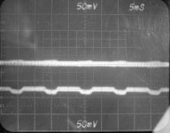
>> OK, so if I understand correctly, you can see noise on the output but it's principally ripple, not hash? If so, that's a good sign! It means it's now all down to grounding and layout. <<
Yes and no I'll add a picture, I squint some hiss noise, do you agree ?
>> If you have (or can get) a copy of Bob Pease's superb book on analog troubleshooting, the paper is published as an appendix. <<
What's the exact title of the paper, I will try to locate it on the net.
>> No, you've already bypassed the ADJ pin- the 100R has a pretty low noise compared to that big voltage set resistor. I would just go higher on the current and go higher on the cap values. <<
I don't think I am dealing with resistor noise or LM317 noise at the moment yet,
now current is 5mA = 240R, where would you go to ?
For Caps, if big caps --> lower bandpass freq. then
why I get ripple with C4 = 3.3uF ?
BTW which low noise PS do you use ?
top trace = R ch output, AC coupled
bottom trace = 310 V PS at Board output, AC coupled
Regards
Attachments
- Status
- This old topic is closed. If you want to reopen this topic, contact a moderator using the "Report Post" button.
- Home
- Amplifiers
- Tubes / Valves
- Dynaco Pas 3 Hiss from HV regulator