hi,
Im trying to use an lm317 for a CCS for a LTP. Right now I'm just experimenting, and starting w/ the basics, so I'm trying to do the most simple connection w/ the 317 and one resistor to set the current.
So, despite this being a simple 2 component circuit, I can't get it to work!
Pin 1 - adj - goes to resistor which connects to pin2 - out to set the current
pin 2 - out - is connected to ground (as well as the resistor from the adj pin)
pin 3 - in - goes to the LTP
Power it on, and nothing. There isn't much that could go wrong w/ this circuit! Can anyone think of anything I might have missed? Is there a way to test this lm317 w/ a multimeter?
thanks!
wicked1 said:Is there a way to test this lm317 w/ a multimeter?
Take it out of the bigger circuit and hook it up with a 9V battery and a current meter. My guess would be that you have the wrong size resistor which is resulting in very very low current.
Ok,
I finally found a 9 volt battery, and 200ohm resistor is definitely giving me 7ma.
What else could be wrong? I guess I'll briefly explain the rest of the circuit.
There's a triode input stage w/ LED bias. That goes to this 12at7 LTP, which goes to triode wired 6v6 outputs.
W/ the CCS in place, the LED does not light on the input triode.
I put the resistor back in the tail, and the amp works fine again, so I'm sure I didn't mess something else up.
The plate resistors are of equal value. (and that even seems to work w/ the resistor instead of the current source)
Any ideas?
Hi Wicked
Which valves are you using for the LTP? Are the grids at ground level? Are you using a negative voltage?
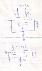
If the grids are at ground level and you have no negative voltage (which I imagine is your situation) you can only work with low mu valves (6SN7, etc), as they cab have a high enough Vgk for the LM317 to work properly (the LM317 needs at least ~3,75VDC across it to work properly) Also the LM317 needs to conduct at least 5mA!
But, well, just change one thing in your CCS: connect the adjust to ground, and disconnect the output. Yes, the output should not be connected to anything with exception of the current setting resistor.
Chech figure 26 in this datasheet
Good luck, Erik
Which valves are you using for the LTP? Are the grids at ground level? Are you using a negative voltage?
If the grids are at ground level and you have no negative voltage (which I imagine is your situation) you can only work with low mu valves (6SN7, etc), as they cab have a high enough Vgk for the LM317 to work properly (the LM317 needs at least ~3,75VDC across it to work properly) Also the LM317 needs to conduct at least 5mA!
But, well, just change one thing in your CCS: connect the adjust to ground, and disconnect the output. Yes, the output should not be connected to anything with exception of the current setting resistor.
Chech figure 26 in this datasheet
Good luck, Erik
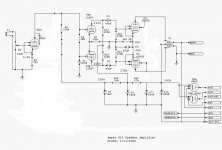
Here's the schematic. It's a modified ampex 612. Some of you probably answered my question a few weeks ago about what I should do to modify it. This is what I've done so far.
I didn't completely finish modifying hte schematic. The plate resistors on the LTP are both 110k ohm, there's an LED in place of the cathode resistor on the input tube, and the LTP tube is a 12aT7, not aU7.
thanks again
I didn't completely finish modifying hte schematic. The plate resistors on the LTP are both 110k ohm, there's an LED in place of the cathode resistor on the input tube, and the LTP tube is a 12aT7, not aU7.
thanks again
Attachments
So you want to substitute R2 (82k) for the LM317 CCS? The LM317 can only withstand 37V across it, and in this application you have surely way more than that (the grids are at 80V, so the cathodes are even somewhat higher.
You still can use the LM317 however, for example by connecting a 60V zener (look at dissipation: P = V*I) in series with it, or otherwise a resistor (R = 60V/current CCS).
Good luck, Erik
You still can use the LM317 however, for example by connecting a 60V zener (look at dissipation: P = V*I) in series with it, or otherwise a resistor (R = 60V/current CCS).
Good luck, Erik
Thank you so much.. I was just realizing this myself, but wasn't sure.
I was about to pull out the datasheet.
Hurm.. Maybe I'll remove the first tube, and try going from my audio source directly into the LTP, as someone mentioned in my previous thread.
That was the first thing I tried, but it didn't have enough gain. I've since made several other changes, so it might be worth trying again.
wicked1 said:Here's the schematic. It's a modified ampex 612. Some of you probably answered my question a few weeks ago about what I should do to modify it. This is what I've done so far.
I didn't completely finish modifying hte schematic. The plate resistors on the LTP are both 110k ohm, there's an LED in place of the cathode resistor on the input tube, and the LTP tube is a 12aT7, not aU7.
thanks again
In such a schematic case, Erik is right, you will need a zener. But LM317 isn't good for HF. Utilize a full BJT cascode referenced to some -V, if you have to do it. It will stand the voltage too. Use 60V transistors.
can I do the BJT cascode w/out a negative supply? That's honestly the primary reason I didn't start w/ that circuit.
edit (sorry, just re-read your post and see that you say referenced to - , so that answers that)
I guess at this point I should probably just jump in. I wanted to make a few simple changes, but it's getting closer to a complete rebuild.
Then the question becomes how simply and how small (physically) can I make the negative supply? The amps are already in cases and I don't have a lot of room to work.
Couple of problems here. First, as others have said, you're violating the voltage rating of the chip. Second (maybe first, actually), the LM317 is a voltage regulator, not a current source.
Try the IXYS IXCP 10M45S in this application. You'll be actually out the bottom of its ratings a little, but I've not found this to be a problem, and there's a good deal of experience around here with them.
I've also found that, both for channel matching and experimentation, using a trimmer pot in the control circuit is advisable. I use a 248Ω resistor and a 100Ω 12-turn pot for my app.
Aloha,
Poinz
- Status
- This old topic is closed. If you want to reopen this topic, contact a moderator using the "Report Post" button.
- Home
- Amplifiers
- Tubes / Valves
- lm317 CCS question