The LTP inverter is quite accurate and has good balance, but it's not perfect. Adding a CCS at the bottom will not make it perfect either. As the CCS maintains a constant current flow, whatever one tube increases by, the other tube decreases by. This alone does not result in perfect balance. You can still have imbalance in the pair of triodes used so you should try and source a balanced twin triode (both sections match well). If you want to get the best performance, in addition, I would use a linear pot in the plate circuit as an AC balance control, best adjusted using a distortion analyzer.
Regards, KM
Regards, KM
You can still have imbalance in the pair of triodes used so you should try and source a balanced twin triode (both sections match well).
With a good CCS as the tail, the triodes should be able to be thoroughly mismatched and the balance will still be as perfect as the loads. Think about it: if the current IS constant (and even in a cheap bipolar cascode CCS, the current is VERY constant), any decrease in one plate current MUST have an equal and opposite response in the other, otherwise Kirchoff's Law is violated. There's no other place for the current to go as long as the stage is not overloaded.
kmaier said:The LTP inverter is quite accurate and has good balance, but it's not perfect. Adding a CCS at the bottom will not make it perfect either. As the CCS maintains a constant current flow, whatever one tube increases by, the other tube decreases by. This alone does not result in perfect balance.
Regards, KM
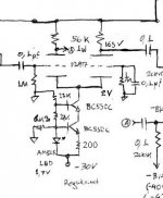
Here is what I use in my amp. Although I could get 5% different DC voltage drops at each plate, for some AT7 tubes in my collection due to differences of gm in the triode pairs, the AC balance was always spot on for AC RMS measurements at the grids of the final stage tubes.
Attachments
Yes, I should probably qualify my statement... if you have different gain tubes you can still get some nonlinear performance, not necessarily inversion balance. You might not see it on a scope but a good analyzer will show it. Also, you're probably doing something with the output of the LTP, either driving a pair of output tubes or pre-drivers. This also implies two devices operating 180 degrees out of phase, but it's very unlikely you will have a perfectly matched pair of outputs, as many are only matched to within 5%. As a result, having an AC balance control is a nice option, and adding DC balance to the output stage is also a nice option... you can actually null distortion and output noise to a considerable degree.
Also, the amount of quiescent current in the LTP should be adequate to drive it's intended load at the voltage swing and bandwidth required for your application (ie, slew rate calculation). In the past, I ran a 6FQ7 LTP with a CCS at 10ma. It was driving a pair of KT-88 in UL-PP and required P-P swings in excess of 150 volts. Bandwidth was flat beyond 30KHz.
Regards, KM
kmaier said:Yes, I should probably qualify my statement... if you have different gain tubes you can still get some nonlinear performance, not necessarily inversion balance. You might not see it on a scope but a good analyzer will show it. Also, you're probably doing something with the output of the LTP, either driving a pair of output tubes or pre-drivers. This also implies two devices operating 180 degrees out of phase, but it's very unlikely you will have a perfectly matched pair of outputs, as many are only matched to within 5%. As a result, having an AC balance control is a nice option, and adding DC balance to the output stage is also a nice option... you can actually null distortion and output noise to a considerable degree.
Also, the amount of quiescent current in the LTP should be adequate to drive it's intended load at the voltage swing and bandwidth required for your application (ie, slew rate calculation). In the past, I ran a 6FQ7 LTP with a CCS at 10ma. It was driving a pair of KT-88 in UL-PP and required P-P swings in excess of 150 volts. Bandwidth was flat beyond 30KHz.
Regards, KM
Very good additional points. Though it may be argued that some residual harmonic imbalance will be mainly of the second order variety, needed somewhat subjectively in a PP amp to counterbalance the predominating 3rd.
For instance by using that LTP I posted, utilizing the particular non linearities of 12AT7, and not taking measures for absolute harmonic balance of the KT88 output stage more than the actual performance that the PP OPTs could achieve, I got the attached distortion spectrum, where 2nd is stronger than 3rd at -72dB vs -80dB.
(test signal peak is at 100dB, 10dB/div).
Attachments
I don't understand these arguments about AC imbalance when using a good CCS. As SY says, it will be just about perfect, and that's even with different TYPES of triode, let alone mismatched triodes of the same type (although there's no purpose in trying such a stunt).  The fact that the sum of the plate currents is constant means that ANY change in the plate current of one tube is matched by an equal and opposite change in the other tube, at ANY point in the waveform.
Now, this is no guarantee of linearity. If you use an unsuitable twin triode like the 12AU7, you're likely to suffer from the non-linearity in one half being reflected in the other half. You can't make a silk purse out of a sow's ear, so you need to use a good audio triode from the word 'GO'.
It's also no guarantee of DC balance, but that can be improved to quite a good degree by using resistors in the cathodes either side of the CCS.
The fact that the sum of the plate currents is constant means that ANY change in the plate current of one tube is matched by an equal and opposite change in the other tube, at ANY point in the waveform. Now, this is no guarantee of linearity. If you use an unsuitable twin triode like the 12AU7, you're likely to suffer from the non-linearity in one half being reflected in the other half. You can't make a silk purse out of a sow's ear, so you need to use a good audio triode from the word 'GO'.
It's also no guarantee of DC balance, but that can be improved to quite a good degree by using resistors in the cathodes either side of the CCS.
kmaier said:The LTP inverter is quite accurate and has good balance, but it's not perfect. Adding a CCS at the bottom will not make it perfect either.
There's no such thing as perfection in the real world. Not. Gonna. Happen. However, an LTP with an active tail load is going to come close enough.
If you want to get the best performance, in addition, I would use a linear pot in the plate circuit as an AC balance control, best adjusted using a distortion analyzer.
That's overkill, and isn't necessary. I've done two LTP splitters using the 6SL7 and cascoded 6BQ7As, both with cascoded BJT CCS. With 1.0% precision metal film resistors for plate loads, there isn't any measureable AC imbalance. Find a good, low distortion loadline, and there simply isn't enough residual distortion to worry about since what's coming off the finals and OPT will be worse anyway.
The LTP splitter was originally designed for precision instrumentation amplification, is still used for that purpose today.
- Status
- This old topic is closed. If you want to reopen this topic, contact a moderator using the "Report Post" button.
- Home
- Amplifiers
- Tubes / Valves
- 12at7 LTP CCS