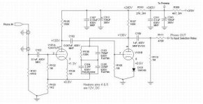
I got at a very good price an almost brand new Copland CTA-402 Integrated Amplifier. Here the phono section for your comments.
It is using great parts quality: Beyschlag film resistors, Phillips MKP capacitors (now Vishay, same as used by Lamm). For the RIAA active feedback network, Phillips foil film and polystyrene caps. The input cap is MKC (I guest polycarbonate) and the output coupling cap is an Evox MKP.
It is using a few nice tricks, one single triode per channel, final section bias using a diode, input triode reference point lift by about the same 0.6V using a resistor, active RIAA network feedback applied directly to the input triode.
I read that this is probably the simpler phono preamp you can build, just one tube per channel. Its mean disadvantage is a rather high output impedance. But in this case, it is not really a problem because it is built into an integrated amplifier with a high input impedance active preamp. The output goes directly to the balance 100K potentiometer, then the volume pot and the preamp input.
I'll gladly receive your comments on this preamp and how it can be improve.
I think the best thing to improve is the output coupling cap, the Evox MKP. I think to bypass it with a 0.1uF Jensen Copper foil and a MK1837.
I'll do some measurements on the RIAA correction curve accuracy tomorrow.
I checked it rapidly using an inverse RIAA network and an input square waveform. It looks perfect at 1Khz.
Let me know what you think.
Thanks in advance.
Attachments
Gut and rebuild. Designer parts are nice, but the basic stage is very problematic, having the same issues as the late and unlamented Dynaco PAS.
1. Input capacitance is high. Many MMs will not be happy, and any sort of MC stepup will suffer.
2. Loading of the 12AX7s is quite low (like 1.5x rp for the first stage), so the open loop distortion will not be very good.
3. Open loop gain is very, very marginal. If you tweak the RIAA feedback for conformance, the low frequency distortion will be quite high.
4. The RIAA network makes the loading issue on the second stage a real problem. Think about what the effective plate load is at high frequencies, where the RIAA caps are low impedance. At low frequencies, the load is better, but still far too low (50k!).
5. The 0.7V diode biasing in the second hole will almost guarantee poor overload performance. Especially at high frequencies, where the second stage will be gasping for air anyway because of the cruel load.
RIAA stages are very difficult to design properly, which is why there are so few good commercial designs. This is not one of them.
SY said:Gut and rebuild. Designer parts are nice, but the basic stage is very problematic, having the same issues as the late and unlamented Dynaco PAS.
1. Input capacitance is high. Many MMs will not be happy, and any sort of MC stepup will suffer.
...
Hi SY,
ups, are you able to tell me a value for the input capacitance?
Thanks.
Kind regards,
Darius
SY said:One other choice- you could probably build up something like Allen Wright's circuit, a FET-tube cascode, inside the Copland.
SY,
AW's JFET "downstairs"/triode "upstairs" seems oriented towards LOMC service. If the phono section is to be mated with a MM cart., could things be better using a 6922 section "downstairs" and a MOSFET, say a ZVN0545A, "upstairs"? With both cathodes of the 6922 close to ground, issues of heater to cathode potential limits are "off the table". Obtaining sufficient gain from the cascode appears to be unproblematic, given 6922 gm of 12.5 mA./V.
Algar, poke around Allen's site (www.vacuumstate.com). Buy his preamp book- it's idiosyncratic, but an interesting and useful read.
Eli, Allen gives parts values for MC and MM. FWIW, I used a circuit very similar to his (but with an NTE458 on the bottom) for about 20-25 years with various MMs. Worked fine in that service. The low input capacitance came in handy when it was time to install an MC stepup when I changed over to LOMC.
Eli, Allen gives parts values for MC and MM. FWIW, I used a circuit very similar to his (but with an NTE458 on the bottom) for about 20-25 years with various MMs. Worked fine in that service. The low input capacitance came in handy when it was time to install an MC stepup when I changed over to LOMC.
From an Allen white paper I got this schematic. It can probably be mounted directly using the existing PCB. For the record I tested the accuracy of the RIAA response of this preamp. It is really good and match perfectly the curve, here some results:
Since there is no preamp output, measured at the output into 8ohms load at 1V output level, 1Khz reference.
Audio generator terminated into 50ohms load. I agree this is not an actual cartridge.
Freq(Hz)Theor(dB) Actual(dB)
50 +16.93 +16.6
100 +13.09 +13.0
200 +8.23 +8.20
281 +5.88 +5.90
398 +3.81 +3.8
500 +2.63 +2.6
1000 0.00 Ref
1413 -1.17 -1.1
1778 -2.07 -2.0
2818 -4.36 -4.2
3981 -6.55 -6.3
5012 -8.18 -8.1
6310 -9.92 -9.8
7943 -11.72 -11.4
10000 -13.55 -13.4
12590 -15.37 -15.3
15850 -17.17 -17.2
19950 -18.89 -19.4
Attachments
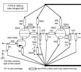
Seems a good choice here. I built something similar based on a design by Steve Bench. The Allen Wright one only needs one dual triode, so would be easy to fit in your chassis. Here's the full article for the schema above: http://vacuumstate.com/various/SP-15_Article.pdf
As shown above, you'll only need the front end. And your RIAA values will be very close if you load it with 50kOhm. You will need a very quiet power supply, as the cascode has no PSRR to speak of. Or, of you are up for it, you can try some noise canceling techniques, as described here: http://www.tubecad.com/march99/.
Sheldon
Algar_emi said:This is why Allen recommended to use his Shunt regulator to supply the preamp. I guest it provides a very low noise supply.
Yes, that would be a good choice.
Sheldon
#4
Hello Algar_emi
keep your eyes open!
@SY: I am still waiting for an answer on post #3 .
Kind regards,
Darius
Originally #4 posted by Algar_emi
Thanks SY for the comments. Very informative indeed. ...
Hello Algar_emi
keep your eyes open!
@SY: I am still waiting for an answer on post #3 .
Kind regards,
Darius
Re: #4
Is there something you want to add to the topic, or do you want to make a statement about SY?
If it's the former, my guess would, assuming a gain of around 50, be about 100pf. That assumes that the data sheet values are accurate. Measured values might be considerably higher.
If that's wrong or missing the point, hold your nose, climb into the sty with we pigs and teach us.
Sheldon
oldeurope said:
Hello Algar_emi
keep your eyes open!
@SY: I am still waiting for an answer on post #3 .
Kind regards,
Darius
Is there something you want to add to the topic, or do you want to make a statement about SY?
If it's the former, my guess would, assuming a gain of around 50, be about 100pf. That assumes that the data sheet values are accurate. Measured values might be considerably higher.
If that's wrong or missing the point, hold your nose, climb into the sty with we pigs and teach us.
Sheldon
Keep your eyes open!
Please cool down Sheldon.
Nobody is able to tell you the input capacitance of this circuit because it depends
in the frequency. This is an active RIAA  and it has negative feedback to the
cathode of V101A. Means the higher the sound frequency the more signal voltage
drops at R103. Thus, the higher the sound frequency the lower the gain and the
capacitance of the input stage.
A high input capacitance makes a low input impedance at high sound frequencies.
In this circuit the input capacitance is fairly low at high
frequencies.
Worst case calculation for 20KHz:
Over all gain 20dB this is vu = 10 = vu[V101A] x vu[V101B]
Gain of V101B lvul >1 , thus the gain of V101A lvul< 10
Miller capacitance of V101 is 1,6pF
C input = (lvul +1) x C Miller
C input @20KHz < 18pF
Have a look at the MM data sheet, they will be happy, maybe you need an additional
cap at the input. MC stepups will not suffer.
Kind regards,
Darius
Originally #14 posted by Sheldon
Is there something you want to add to the topic, or do you want to make a statement about SY?
If it's the former, my guess would, assuming a gain of around 50, be about 100pf. That assumes that the data sheet values are accurate. Measured values might be considerably higher.
If that's wrong or missing the point, hold your nose, climb into the sty with we pigs and teach us.
Sheldon
Please cool down Sheldon.
Nobody is able to tell you the input capacitance of this circuit because it depends
in the frequency.
This is an active RIAA and it has negative feedback to thecathode of V101A. Means the higher the sound frequency the more signal voltage
drops at R103. Thus, the higher the sound frequency the lower the gain and the
capacitance of the input stage.
A high input capacitance makes a low input impedance at high sound frequencies.
In this circuit the input capacitance is fairly low at high
frequencies.
Worst case calculation for 20KHz:
Over all gain 20dB this is vu = 10 = vu[V101A] x vu[V101B]
Gain of V101B lvul >1 , thus the gain of V101A lvul< 10
Miller capacitance of V101 is 1,6pF
C input = (lvul +1) x C Miller
C input @20KHz < 18pF
Originally #2 posted by SY
1. ...Input capacitance is high. Many MMs will not be happy, and any sort of MC stepup will suffer. ...
Have a look at the MM data sheet, they will be happy, maybe you need an additional
cap at the input. MC stepups will not suffer.
Kind regards,
Darius
Re: Keep your eyes open!
I'm not hot Darius. I just find the passive/aggressive approach tedious. Clearly you had something to say about the subject (interesting, as it turns out - and I expected that, as you have described some interesting approaches in other threads), so just say it straight out. Even the blunt approach is fine, I have no problem with that - won't hurt my feelings.
Sheldon
oldeurope said:Please cool down Sheldon.
Nobody is able to tell you the input capacitance of this circuit because it depends
in the frequency.
cathode of V101A. Means the higher the sound frequency the more signal voltage
drops at R103. Thus, the higher the sound frequency the lower the gain and the
capacitance of the input stage.
A high input capacitance makes a low input impedance at high sound frequencies.
In this circuit the input capacitance is fairly low at high
frequencies.
Worst case calculation for 20KHz:
Over all gain 20dB this is vu = 10 = vu[V101A] x vu[V101B]
Gain of V101B lvul >1 , thus the gain of V101A lvul< 10
Miller capacitance of V101 is 1,6pF
C input = (lvul +1) x C Miller
C input @20KHz < 18pF
Have a look at the MM data sheet, they will be happy, maybe you need an additional
cap at the input. MC stepups will not suffer.
Kind regards,
Darius
I'm not hot Darius. I just find the passive/aggressive approach tedious. Clearly you had something to say about the subject (interesting, as it turns out - and I expected that, as you have described some interesting approaches in other threads), so just say it straight out. Even the blunt approach is fine, I have no problem with that - won't hurt my feelings.
Sheldon
I'll follow up with a measurement a little later, just to nail things down, but the analysis makes several assumptions that are not the case here, especially as regards the second stage gain and output impedance, and how that affects the actual amount of feedback at high frequencies. I'd explain a bit more now, but I hate getting into tedious stuff.
Hello Sheldon thanks for post #16. I am looking forward to see your measurements, SY .
The next point that confuses me is this one:
I agree that loading is like 1,5 x rp but this stage has a low signal level and negative
current feedback caused by R104 + R103. Copland schematic
Now comes a strange thing, SY recommends a cascode input.
See link
The loading down in a cascode topologie is very strong, it is like a short circuit.
Thus the Copland input topology is the better choice.
Kind regards,
Darius
The next point that confuses me is this one:
I think rp is the differential resistance between anode and cathode of the triode.Originally #2 posted by SY
... 2. Loading of the 12AX7s is quite low (like 1.5x rp for the first stage), so the open loop distortion will not be very good. ...
I agree that loading is like 1,5 x rp but this stage
has a low signal level and negativecurrent feedback caused by R104 + R103. Copland schematic
Now comes a strange thing, SY recommends a cascode input.
Think about how much is the load of the bottom triode or FET in a cascode?Originally #5 posted by SY
One other choice- you could probably build up something like Allen Wright's circuit, a FET-tube cascode, inside the Copland.
See link
The loading down in a cascode topologie is very strong, it is like a short circuit.
Thus the Copland input topology is the better choice.
Kind regards,
Darius
Re: #4
Darius, a maximum current of 8mA cannot be achieved under "normal" circuit conditions. To maintain the <1W plate dissipation, 125V at 8mA is the highest possible plate voltage, which would coincide with a very-positive bias. There is a reason why most 12AX7 plate curve plots end at ~4 mA. The 0 grid voltage line intersects 75% dissipation in that territory, suggesting no "normal" applications. If >2mA is needed, I'd look for a pentode or cascode instead to achieve high gain.
Cheers,
Jon
oldeurope said:
Darius, a maximum current of 8mA cannot be achieved under "normal" circuit conditions. To maintain the <1W plate dissipation, 125V at 8mA is the highest possible plate voltage, which would coincide with a very-positive bias. There is a reason why most 12AX7 plate curve plots end at ~4 mA. The 0 grid voltage line intersects 75% dissipation in that territory, suggesting no "normal" applications. If >2mA is needed, I'd look for a pentode or cascode instead to achieve high gain.
Cheers,
Jon
OK, I'll admit that I cheated a bit- having the advantage of age and sad experience, I recognized this circuit as one more PAS variation. And since building my first one in 1968, I've gone through about every variation possible. So it's not like I didn't already know the outcome...
Anyway, I grabbed a PAS board and did a few mods to simulate this circuit. I added the input coupling cap (a really poor idea wrt low frequency noise) to accommodate the DC lift that the alternate feedback connection requires. The feedback circuit is the same at high frequencies- it's a little different at LF, but that's not the focus of this measurement. There's no 47k resistor at the input so that the input capacitance could be easily measured.
Using a 10kHz excitation and a Leader LCR740 cap bridge, I measured Cin at 112pF, pretty close to the expected value. I didn't measure 10kHz distortion this time, but from having done it with similar circuits a few dozen times before, I can say with confidence that it ain't pretty, and contrary to the simple and wrong feedback model, the distortion rises with frequency.
Regarding cascodes, you might want to review FET operation and maybe stoop to actually doing some bench testing. Allen Wright has published his results and they are quite impressive. I'll let you explain to him why he's doing it all wrong.
- Status
- This old topic is closed. If you want to reopen this topic, contact a moderator using the "Report Post" button.
- Home
- Amplifiers
- Tubes / Valves
- Copland CTA-402 Phono Section Comments