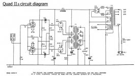
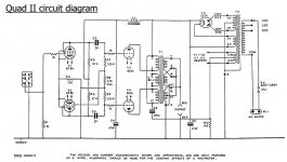
Having two old QuadII, that I personally do not enjoy listening to, and a good supply of NOS 6B4G lying around I am just about to start rebuilding.
I have already taken the OPTs out of their cans by cooking them for a few hours at 150 degrees C to melt the goo.
As the 6B4G can not be loaded with 3350ohms in PP I will rewire the secondaries adding some extra soldering tags. This makes it possible to try 7600:8ohm instead. Wired for the original 8ohm connection will load the primary with 6700ohms when used with a 16ohm load.
If the first try works out like I hope, the next step is to change the EF86s for 5842 or 6C45. After that I will also try rewiring the primary and omit the cathode feedback windings. This will load the primary with 6100ohms with 8ohm load instead. With 16 ohm load on the original 8ohm connection the load will be 5500ohm.
As the amp will be used for midrange horns the lows are not important.
Attachments
I would not be so quick to remove the cathode feedback. If I recall correctly, the each cathode feedback coil is about 15%. If this is the case, then by using them it will effectively drop the 6B4's Mu to 2.5, and its plate impedance to 480 ohms. This way you would not have to mess around with using different secondary taps to get the desired reflected primary impedance.
Rgs, JLH
Rgs, JLH
Thank you guys for your comments!
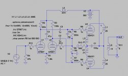
EC8010: Didn´t you read the first schematic? What do think 6VDC 1 and 6VDC 2 means") ?
?
JLH: If you also read my text carefully the first try will be with the cathode feedback. My concern about not using it, is that the demands on the driver gets very high with the windings in place depending on, as you say, that mu is lowered.
The anode-winding is 2880 turns and the cathode-winding is 320 turns. This would mean the mu and Rp isn´t lowered that much, I guess?
Brgds
Lars
EC8010: Didn´t you read the first schematic? What do think 6VDC 1 and 6VDC 2 means
? JLH: If you also read my text carefully the first try will be with the cathode feedback
. My concern about not using it, is that the demands on the driver gets very high with the windings in place depending on, as you say, that mu is lowered. The anode-winding is 2880 turns and the cathode-winding is 320 turns. This would mean the mu and Rp isn´t lowered that much, I guess?
Brgds
Lars
Consider using DHTs throughout. For instance the 3a5 in the first two positions. You can then build a balanced amp all through, and for example direct couple stage one to stage 2, then transformer couple to the outputs with Lundahl LL1660 or similar. Again, you will need seperate filament supplies for each 3a5. You would need to consider a second chassis for the filament supplies.
All DHT amps are pretty awesome in terms of detail and delicate treble.
All DHT amps are pretty awesome in terms of detail and delicate treble.
Andyjevans: Thanks for your concern! The whole idea is to rebuild the Quad without adding any extra boxes. Also I want to keep as much as possible the original topology with only two gain stages. So an IT(though it crossed my mind ) is out of the question, as is the 3A5 that has to low mu, lousy linearity and low Uamax for this application.
Brgds
) is out of the question, as is the 3A5 that has to low mu, lousy linearity and low Uamax for this application. Brgds
JLH: After reading your post again, I realize that I don´t fully understand what happens impedance-wise with the cathodewindings in place. Could you please help to clarify. What will the reflected primary impedance be?
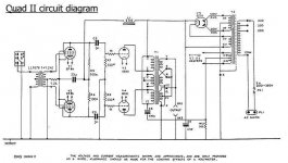
Any how I did a spice sim of the circuit and the EF86s are in trouble ! It is hard to get enough headroom.
Any how I did a spice sim of the circuit and the EF86s are in trouble
! It is hard to get enough headroom.Attachments
andyjevans said:All DHT amps are pretty awesome in terms of detail and delicate treble.
Only people under the age of thirty are allowed to use the word "awesome".
Discovered the HT CT and the heater CT are connected inside the mains transformer. So I will have to "cook" that one too.
Meanwhile I have made some adjustments to the schematic:
Found Pete Milletts 6B4G-PP schematic and decided to try his cathode-resistor arrangement.
Meanwhile I have made some adjustments to the schematic:
An externally hosted image should be here but it was not working when we last tested it.
Found Pete Milletts 6B4G-PP schematic and decided to try his cathode-resistor arrangement.
hey-Hey!!!,
The cathode windings are counted just like plate windings for the load. So additional turns [(2880+320)/2880]^2 and multiply that number by the plate winding impedance determined earlier( 1.234 *____) that looks like 4k1 of load plus you get an 11% CFB to drop the output Z further.
cheers,
Douglas
The cathode windings are counted just like plate windings for the load. So additional turns [(2880+320)/2880]^2 and multiply that number by the plate winding impedance determined earlier( 1.234 *____) that looks like 4k1 of load plus you get an 11% CFB to drop the output Z further.
cheers,
Douglas
Hmm...
I really feel like the odd ball here... cause I want to say... HEY Whoa! what! Don't ruin 2 vintage amps! And yes I do mean ruin... the quad is a classic... you can't change it much at all without ruining it (its value as a vintage amp). If you want to build a DHT amp, then start from scratch. Keep the quads as is... as they are supposed to be... cause honestly... no one really cares what you do with a DHT... I don't mean that in a bad way.. but the quad is a rare piece of history at this point, your DIY is not (at least not yet). I mean it's such a massive rebuild anyway.. just skip back to square one, and keep your $$$money vintage amps too. I hope that doesn't sound as bad as it sounds...
I really feel like the odd ball here... cause I want to say... HEY Whoa! what! Don't ruin 2 vintage amps! And yes I do mean ruin... the quad is a classic... you can't change it much at all without ruining it (its value as a vintage amp). If you want to build a DHT amp, then start from scratch. Keep the quads as is... as they are supposed to be... cause honestly... no one really cares what you do with a DHT... I don't mean that in a bad way.. but the quad is a rare piece of history at this point, your DIY is not (at least not yet). I mean it's such a massive rebuild anyway.. just skip back to square one, and keep your $$$money vintage amps too. I hope that doesn't sound as bad as it sounds...
Hi Douglas,
Your totally wrong about my OPTs, but about a standard QII tranny you are right! Check the schematic again:
1 The CFB is not used. The reason for this is that the drivers are not capable of deliver the swing needed.
2. The secondaries are totally rewired so we have 2880:102 which means 6380:8 ohms. If it is 2880:104 we get 6150:8 ohms. There is another thread about the Quad OPT here: http://www.diyaudio.com/forums/showthread.php?s=&threadid=121217
Hi Sean,
Thanks for your concern. Remember I live in Europe. QuadIIs aren´t that uncommon here and my pair was not in mint condition when I got them. And...... it is not a massive rebuild: You can wire them back to the boring, laid back sounding originals in a few hours and noone could tell they where ever rebuilt. About vintage, I am a retro guy, check my site: www.revintage.se.
Your totally wrong about my OPTs, but about a standard QII tranny you are right
! Check the schematic again:1 The CFB is not used. The reason for this is that the drivers are not capable of deliver the swing needed.
2. The secondaries are totally rewired so we have 2880:102 which means 6380:8 ohms. If it is 2880:104 we get 6150:8 ohms. There is another thread about the Quad OPT here: http://www.diyaudio.com/forums/showthread.php?s=&threadid=121217
Hi Sean,
Thanks for your concern. Remember I live in Europe. QuadIIs aren´t that uncommon here and my pair was not in mint condition when I got them. And...... it is not a massive rebuild: You can wire them back to the boring, laid back sounding originals in a few hours and noone could tell they where ever rebuilt
. About vintage, I am a retro guy, check my site: www.revintage.se.- Status
- This old topic is closed. If you want to reopen this topic, contact a moderator using the "Report Post" button.
- Home
- Amplifiers
- Tubes / Valves
- QUADII with DHT