I just finished my ST70 build and powed it up. I dont blow any fuses and the tubes glow with none of them being dimmer or brighter than the others.
The problem is that I have no output.
I am checking over everything again but was wondering if anyone had any suggestions on where to pay special attention.
Im also a little confused on how the 500k pots should be set because the diytube.com instructions make no mention of them.
The problem is that I have no output.
I am checking over everything again but was wondering if anyone had any suggestions on where to pay special attention.
Im also a little confused on how the 500k pots should be set because the diytube.com instructions make no mention of them.
I thought that I possibly had the bias pot wires switched around so I swapped them.
Now when I hook up my meter to bias I hear static out of the speakers.
I also have a faint hum now from the speakers, so I think I am on the right track. The problem must be in the input section. I will be looking for a problem there, still open to suggestions, though.
Now when I hook up my meter to bias I hear static out of the speakers.
I also have a faint hum now from the speakers, so I think I am on the right track. The problem must be in the input section. I will be looking for a problem there, still open to suggestions, though.
You'll need to check the voltages against the chart in the manual. Post your results here, and maybe someone can spot the problem. Be sure to make a post on the diytube.com forum as well.
A hi-res photo of the board and wiring wouldn't hurt, either.
In a perfect world, the 500k pots on the driver board should be set exactly in the middle. They balance the bias voltage to each side of the push/pull pair of output tubes. If the tubes are well matched, the pot should end up pretty close to centered.
I think the pot is a ten-turn job. Trying to center it by counting turns would be tricky. You could probably meter it out (with the power off) and check to see if each side is roughly 250k.
burnedfingers said:Pictures would help.
Also, what driver board did you use? Is this a rebuild of a stock Dynaco or is it an aftermarket kit?
Its all aftermarket. For the power supply section I bought triodeel.coms board. For the driver board I built the diytube.com board using point to point wiring.
As for a picture...Ill admit, I got too small of an enclosure so even the most knowledgable expert would have trouble looking at a picure of this nest of wires. Im proud to say even working in such small spaces and using a large soldering gun I did not burn any wires insulation.
I just replaced the bias pots and got a new battery for my meter.
I took some measurements and I cant get any bias voltage and all of the pins with high dc voltage is up over 500VDC.
On the el34's I am supposed to get -35V on two spots. I get it on one but not the other. (actually, the voltage chart says pins 5 and 6 but 6 is not used so I am probably ok here.)
On the power supply board the 300 and 350VDC lugs are reading over 500VDC.
Any ideas? Thanks for any input.
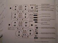
burnedfingers said:Is this the power supply board?
Yes, thats the one I am using.
This is the drive board section. http://www.diytube.com/st70/diytube_st70_B.pdf
One of my probes for my meter broke so another setback. Ill have to wait until I can grab my other one from work tommorrow to take more measurements.
Did you ground the power supply board to the grounding point on the chassis? Did you ground the driver board to the same point?
OPT on power supply board to feed both red wires on output transformers.
Pad #20 on power supply board to #20 on driver board.
Pad #19 on power supply board to #19 on driver board.
As you are looking at the back of the bias pot ( shaft away from you) the left terminal goes to the R on the board.
"L" on the board goes to the right terminal when the shaft is away from you.
Did you ground the power supply board to the grounding point on the chassis? Did you ground the driver board to the same point?
yes
OPT on power supply board to feed both red wires on output transformers.
yes
Pad #20 on power supply board to #20 on driver board.
yes
Pad #19 on power supply board to #19 on driver board.
yes
As you are looking at the back of the bias pot ( shaft away from you) the left terminal goes to the R on the board.
"L" on the board goes to the right terminal when the shaft is away from you.
I may have screwed up here. Is this with the shaft way from me and the terminals down or up?
yes
OPT on power supply board to feed both red wires on output transformers.
yes
Pad #20 on power supply board to #20 on driver board.
yes
Pad #19 on power supply board to #19 on driver board.
yes
As you are looking at the back of the bias pot ( shaft away from you) the left terminal goes to the R on the board.
"L" on the board goes to the right terminal when the shaft is away from you.
I may have screwed up here. Is this with the shaft way from me and the terminals down or up?
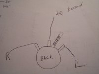
burnedfingers said:picture
Hope this helps
Assuming in that pic the L means its going to the L on the power supply board and R for R, then thats how I have it.
JayH3 said:I took some measurements and I cant get any bias voltage and all of the pins with high dc voltage is up over 500VDC.
Huh? Go read the biasing procedure on page 8. This is a very important procedure. Note step one, where you remove the rectifier tube (5AR4, or GZ34).
You should make absolutely certain you've got sufficient bias voltage (-55 volts) before you allow the high voltage B+ (the 500 volt stuff) to get near the output tubes. If you aren't confident the bias supply is working properly, don't install the 5AR4!
Finally got back to this project today.
I got the amp playing music but still have some other issues.
There is a constant hum that is about the same level as the music. I am guessing its a grounding issue so thats what I am looking for. Anything else I should look for?
Also, the schematic shows the COM speaker terminal grounded, but when I ground them there is a whole new very loud hum. Whats the deal with that?
- Status
- This old topic is closed. If you want to reopen this topic, contact a moderator using the "Report Post" button.
- Home
- Amplifiers
- Tubes / Valves
- Problem with my ST70 build