So would i be right in thinking that if i used a single 6922 tube set up in SE mode with one of the two triodes inside the envelope acting as a CCS hanging off the positive rail and being fed by a 160V supply, the heater voltage would be safe at an offset of 45V???
This will place the amplifying triode's cathode at -45V, while the CCS's cathode would see quiscent around +35V with a swing from 115V to -45V??
Am i correct in thinking this will be okay and not cause any problems?
Leigh
This will place the amplifying triode's cathode at -45V, while the CCS's cathode would see quiscent around +35V with a swing from 115V to -45V??
Am i correct in thinking this will be okay and not cause any problems?
Leigh
I was kinda hoping for one of the forum experts to chime in here...
But such non-appearance notwithstanding, my advice would be: If you have to raise them up in order to stay within spec, then I would elevate it.
They tend to work for a while, but at a cost of slightly increased noise (small enough only to be quite important in a phono stage); but as well, there could be valve-lifetime (longevity) issues to consider. -- It might go distinctly noisy after only 12 months (or even fail). By all means try it and see. 'Cause if it keeps working, great! But If you go through more than a tube a year, you might know where to look first within your circuit.
Electro Harmonix, the manufacturers of my tube say its good to plus/minus 200V. Do you think i'm O.K to go on this advise or would you advise me to still raise the heaters about halfway? The feed to the whole circuit is only 150V so according to EH all should be rosey but most other data sheets say different. This is really confusing me now. !! WAAA!!
Leigh
PS if i stay within the data sheet specs will i have any lifetime issues??
Leigh
PS if i stay within the data sheet specs will i have any lifetime issues??
One good way is a tube tester. Another is it doesn't perform correctly in a known good circuit. There are a bunch of possible symptoms for a bad tube. I haven't had any go bad, so far. When I got my first tube amp, one of the power tube's getter was all white and flaky. That was definitely a bad tube. Other than that, I don't have much experience listening to them as they go bad.
I would think that you should be fine if you are within your tube manufacturer's specs, assuming they spec'd their tubes correctly. However, it's safest to keep heater and cathode reasonably close. It's up to you. It'll just cost you another cheapie 6.3v transformer is all.
I would think that you should be fine if you are within your tube manufacturer's specs, assuming they spec'd their tubes correctly. However, it's safest to keep heater and cathode reasonably close. It's up to you. It'll just cost you another cheapie 6.3v transformer is all.
Any of: a noticeable increase in audible distortion, reduced volume or 'muted' sound, lack of dynamics, lack of 'sparkle' in the highs, and of course declining performance specifications-wise in the circuitnitrate said:How do i know when my tubes are wearing out?? I mean, what are the symptoms.
Aside from ensuring the filament voltage never rises above 6.3v (assuming a 6.3v tube of course!), the best way to promote tube longevity is to have some kind of a soft-start of the PSU.
This could be as simple as just using a tube rectifier, or a thermistor, or a variac, all the way up to separate fil & B+ switches, and dedicated voltage ramp-up circuits.
nitrate,
For your possible interest: The Aikido Board from John Broskie (Tubecad) does much of what you have tried out above.
You can see all of John Broskies writings about this and other circuits here:
http://www.tubecad.com/
Specifically
The AIKIDO Board
The low voltage variant
http://www.tubecad.com/2008/01/blog0132.htm
The original circuit
http://www.tubecad.com/2004/blog0011.htm
The ZENKIDO
http://www.tubecad.com/2007/10/blog0123.htm
The Aikido Board coupled to a Nelson Pass Inspired MOSFET Output Stage.
The blog has links to the AudioExpress article
The MOSKIDO
http://www.tubecad.com/2007/06/blog0111.htm
The Aikido Board with a Push Pull Class A MOSFET Output Stage.
Cheers,
Ian
If you like some more theory as opposed to practical circuit reviews, (i.e. besides Morgan Jones, Alan Wright, Garry Pimm, et. al.); Walt Jung published a couple of articles last year that discuss silicon-based PSU sources and sinks. You can find both of them on his page herenitrate said:Thanks for your input majestic, Seems people's opinion on the 'sound' of CCS topologies differ. I'm gonna see if i can find some more info before i make a final decision on using them or not.
After much deliberation i have decided on this design. The CCS's are made up out of triodes. Whilst this does not give a perfect constant current it does allow for a large signal swing and also ensures that there are no silicon Kinks to distort the sound. I have opted for inter stage capacitor coupling. Most ppl do not like the idea of cap coupled stages but i think the possibility of having the coupling caps alter the sound is offset by the advantage of not having the sines compressed by the loading of the previous stage by both grid leakage and capacitance. The effect of direct coupling with just resistors give a suprisingly high degree of upper half signal compression that is clearly visible on the scope. Three triode stages ( two for amplification and one for buffering ) gives me the overall gain i want plus the ability to throw in a touch of feedback mainly to controll gain over multiple channels and counter the affect of the varying gain over different tubes. This also has the desired side effect of correcting the signal's phase at the output and also ( call me sad ) gives me three shiney glowing tubes per channel to display on top of the amplifier 
Power supply rejection is going to be dire due to the rubbish performance of the CCS's so use of a linear supply or massive capacitance will be nessasary. I'll try RC first but i think i'll end up being forced to use Linear. Plate HT is derived from a voltage doubler and RC network to give me the desired 20mA of current with very low ripple. Power output will be set to 30Wrms in class A then upwards and onwards in classAB. 100Wab should be possible before things either blow up or voltage rails clip. Two pairs of BUZ900/5 should suffice but i'll add more if i get problems. A prototype of a simpler version of this circuit works very well on the bench and this circuit sims good with quite low distotion, although my sim somtimes makes things up in that department. This circuit fulfills all my original design goals of just below line level input to full output amplification, 50Wrms or more of power with a minimum of 30W in 'A', no input/output transformers, no presets, fairly low voltage, no exotic power supply transformers, no transistors directly or indirectly along the signal path. The only objective i failed in is No Feedback. I thought is nessasary to use a little to avoid wildley different gains from varying Mu in the tubes. The feedback employed here has too many advantages to avoid using it, after all it is a very small amount used and can be removed along with the first stage if one desires. On the bench i cant tell its there, unlike the huge wads of feedback i used to employ in my SS designs.
Here's the circuit for you all to poke fun at")
Regards
Leigh
Power supply rejection is going to be dire due to the rubbish performance of the CCS's so use of a linear supply or massive capacitance will be nessasary. I'll try RC first but i think i'll end up being forced to use Linear. Plate HT is derived from a voltage doubler and RC network to give me the desired 20mA of current with very low ripple. Power output will be set to 30Wrms in class A then upwards and onwards in classAB. 100Wab should be possible before things either blow up or voltage rails clip. Two pairs of BUZ900/5 should suffice but i'll add more if i get problems. A prototype of a simpler version of this circuit works very well on the bench and this circuit sims good with quite low distotion, although my sim somtimes makes things up in that department. This circuit fulfills all my original design goals of just below line level input to full output amplification, 50Wrms or more of power with a minimum of 30W in 'A', no input/output transformers, no presets, fairly low voltage, no exotic power supply transformers, no transistors directly or indirectly along the signal path. The only objective i failed in is No Feedback. I thought is nessasary to use a little to avoid wildley different gains from varying Mu in the tubes. The feedback employed here has too many advantages to avoid using it, after all it is a very small amount used and can be removed along with the first stage if one desires. On the bench i cant tell its there, unlike the huge wads of feedback i used to employ in my SS designs.
Here's the circuit for you all to poke fun at
Regards
Leigh
Attachments
Assuming you are doing stereo, you could divide up the twin triodes such that both cathode in a single tube see nearly the same voltage. Triode U3A and U1A would be in one tube, and U3B and U1B another tube. And use two separate heater supplies. And bias each supply for minimal heater-cathode voltage difference. The output drivers will have to be shared by the left U2AL and U2AR right channels as one tube, and U2BL and U2BR another tube.
wa2ise,
I've thought of that before but i dont know if cross talk will become an issue having both channels together in one tube at the driver stage. What do you think? If cross talk is not going to be a problem then i agree with you and this should definatly be implemented.
Leigh
I've thought of that before but i dont know if cross talk will become an issue having both channels together in one tube at the driver stage. What do you think? If cross talk is not going to be a problem then i agree with you and this should definatly be implemented.
Leigh
Had anybody tried wiring tube heaters in series? I have six tubes all the same and i was thinking of wiring the heaters all in series then hanging them off a constant current source giving me six sets of 300mA. This would save loads of power and do away with a seperate heater transformer or extra winding on the power transformer. As a bonus the CCS would give the heaters an excellent soft start thus prolonging tube life. Anybody tried this? or does anybody see any potential pitfalls in the idea?
Regards
Leigh
Regards
Leigh
Had anybody tried wiring tube heaters in series? I have six tubes all the same and i was thinking of wiring the heaters all in series then hanging them off a constant current source giving me six sets of 300mA. This would save loads of power and do away with a seperate heater transformer or extra winding on the power transformer. As a bonus the CCS would give the heaters an excellent soft start thus prolonging tube life. Anybody tried this? or does anybody see any potential pitfalls in the idea?
Should work if they are all the same valve type. Could encounter issues between brands or substitutions.
One thing to consider is using series heater valves. These have unusual voltages but constant current demands. They can be had for peanuts because people are afraid of using them.
Shoog
nitrate said:So you dont think i will have any problems with cross talk being transferred along the heaters?
Crosstalk is neglible along heaters/sections.
Are you going to be using a source selector switch? If so, look at that as the source of stereo seperation destroyer.
Cheers!
Ahh... lovely...
I can feel the glow already.. LOL
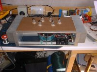
Just an update. I tried wiring each channels heaters in series and running them off a constant current rarther than voltage. The results were very good. It seems the tubes are more balanced now than when i was using constant voltage. They all glow the same and have very close matching Mu. I had them on the test bench wired on constant voltage and some tubes glowed more than others, Mu was also a bit wild from tube to tube. Seems the heaters vary quite a bit in resistance from tube to tube. Anyway things are going ahead nicely as you can see from the piccy below. I've nearly finished the final prototype.
Leigh
I can feel the glow already.. LOL
Just an update. I tried wiring each channels heaters in series and running them off a constant current rarther than voltage. The results were very good. It seems the tubes are more balanced now than when i was using constant voltage. They all glow the same and have very close matching Mu. I had them on the test bench wired on constant voltage and some tubes glowed more than others, Mu was also a bit wild from tube to tube. Seems the heaters vary quite a bit in resistance from tube to tube. Anyway things are going ahead nicely as you can see from the piccy below. I've nearly finished the final prototype.
Leigh
Attachments
BuzzzZZzzzz
Bugger,
I've wired up one half of the channel and powered up. First signs were encourageing. Everything matched the simulation perfectly and soon after a few saftey tests my speakers were being ripped from their chassis. Just a few niggles to clear up i thought. The niggles in uestion were a slight hum and a buzzing noise. The hum was easy, but i cant get rid of this damn buz!!. I dont know were its getting in. If i lift the lid with the valves horizontally the buzz disapears. If i shuffle around the wires connecting the top lid to the main chassis i can cancel out the buz but you have to place them 'just so'. Not a good soloution. I think its rectification either getting on the chassis metal work or being transmitted out of the main transformer wires and being picked up by the rest of the wires. Moving all but the GND wires does nothing but moving ground wires seems to strongly effect the buzzing. The waveform on the scope looks like a fast verticle rise followed by a smooth decay, 100Hz. A bit like a smoothed sawtooth. Thats what makes me belive its coming from the bridge. Anyone any ideas how to combat this buzzing issue?? I dont wanna fall at the last hurdle
Thanks for reading
Leigh
Hmmm....
This Buzz doesnt seem to be radiating from any wires or the transformer as i've tried comleatley encasing the tube section in aluminium to sheild it. Instead of reducing the buzz it actually made it much worse!!
Anyone any ideas about how to track it down, its really doing my head in now??
Leigh
This Buzz doesnt seem to be radiating from any wires or the transformer as i've tried comleatley encasing the tube section in aluminium to sheild it. Instead of reducing the buzz it actually made it much worse!!
Anyone any ideas about how to track it down, its really doing my head in now??
Leigh
- Status
- This old topic is closed. If you want to reopen this topic, contact a moderator using the "Report Post" button.
- Home
- Amplifiers
- Tubes / Valves
- I'm going in.....