
Boris_The_Blade said:
Since (I assume) that this amp is mostly class B, the loadline will be closer to Z/4, or 1250 ohms, putting the Vp=0 at around 440mA. Adjust negative Vg1 so that the 'knee' of the max Vg2 voltage you will have at signal will intersect the loadline (probably near Vp=50V). I believe this will give the best linearity.
Yep, that sounds right, on second thought. It's too easy to forget the effect of the OTHER side on a PP transformer.
I was just conversing with someone else, who had suggested a very slightly negative voltage for g1... and I was thinking of ways to do that. One idea that came to mind, was to "voltage-divide" it... by a resistor from my B- rail (or a dropped-voltage B- rail, to make the resistor ratios a bit more "even") and a resistor from the cathode. That way, the g1 could "track" the cathode a bit, while still biasing the thing downward a bit too. Might help gain go up a tad, as opposed to just tying the g1 to a negative static voltage?
Oooh... an idea... what about putting an LED between g1 and cathode, and a resistor between g1 and the negative rail, to hold g1 at a CONSTANT negative bias voltage relative to the cathode? That should be able to be done at NEGLIGIBLE currents, I would think...
Regards,
Gordon.
Gordon, exactly right, the third dominates, as it should. I still don't get the analogy to bipolars since the Vbe is almost constant and Vg2k is anything but constant.
edit: I tried biasing the grid slightly negative in my 6LF6 screen drive amp and wasn't impressed with the results- it seemed to reduce the mu which was already low.
edit: I tried biasing the grid slightly negative in my 6LF6 screen drive amp and wasn't impressed with the results- it seemed to reduce the mu which was already low.
SY said:edit: I tried biasing the grid slightly negative in my 6LF6 screen drive amp and wasn't impressed with the results- it seemed to reduce the mu which was already low.
This is what I would be afraid of.
I have PLENTY of front-end voltage drive and gain... but there's just about ENOUGH (not really much extra, once a bit of feedback is inserted) gain and voltage drive from the last gain stage to the grids of the output tubes.
I would rather use the extra gain, to allow a greater degree of feedback in the inner feedback loop (between output and driver), than waste it at the output tube g1...
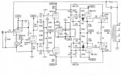
BTW: I've actually made another "subtle" change to the design... since I decided to use a split load phase splitter, it seemed logical to change the second gain stage from grounded cathode to a differential amp. All it required was connecting the two cathodes together, and putting in a CCS... if there WAS any question about balance with a split-load, THAT should take care of it. It'll allow me to get rid of the cathode-follower in the phase splitter... and gave me an obvious route to incorporate feedback to the diff amp gain stage (from the plate of the outputs, to the plates of the diff amp). Even with this, I should still have plenty of voltage (with effectively, a 600-625v available voltage to drive the diff amp)...
Thanks for the continuing assistance!!
Regards,
Gordon.
Attachments
Hello Gordon,
I have been following your screen drive amp design from the beginning with much interest! Are you still in the design stage or have you moved on to the build stage? Assuming you do build the amplifier, I am looking forward to reading about your performance results and listening impressions. I am leaning in the direction of doing one of these designs myself some time in the not too distant future. Thanks! Doug S.")
I have been following your screen drive amp design from the beginning with much interest! Are you still in the design stage or have you moved on to the build stage? Assuming you do build the amplifier, I am looking forward to reading about your performance results and listening impressions. I am leaning in the direction of doing one of these designs myself some time in the not too distant future. Thanks! Doug S.
- Status
- This old topic is closed. If you want to reopen this topic, contact a moderator using the "Report Post" button.
- Home
- Amplifiers
- Tubes / Valves
- 6JN6 screen-drive (g2 driven) plate curves?