Hi all,
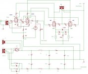
This is my version of Gary Pimms Tabor amp. I was fascinated by the concept of the Tabor because I had done some extensive experiments with the partial feedback design concept and found it to sound very impressive wherever applied. The Tabor might be described as the ultimate partial feedback amp. Most implementations I have ever seen (or built) use triodes in the front end which tend to be run very current starved, this reduces the feedback element as it is what generates the feedback over the feedback resistor. Gary uses the 6AU6 and runs it at a generous 5mA (most run at less than 1mA). He also designed the original to combine the feedback resistor and first stage anode load - this bring sonic benefits. He also went to some trouble to eliminate any coupling caps. The resultant amplifier concept is extremely simple but the only drawback to the original design is that in order to achieve all these wonderful things he also designed a very complex and expensive power supply.
I spent the best part of a year coming at this from various angles. In the end I decided that most of the problems I encountered with the original design can be overcome by having a large split supply. I ended up with a design where I use a +/-300V supply which can easily be derived from a single 330V CT transformer. The negative rail draws about 30mA which makes it an easy thing to design, mine fits on a 4inch x 4inch peg board. The plates of the 6AU6 settle at about 0V. The CCS is the simple ring of two bias block biased up with a 12R resistor. Fresh 807's produce about 40V over the CCS which dissapates about 2.5Watts each - this requires a big heatsink with good air flow (mine currently run at about 70 centigrade which is too high). Over time the voltage over the bias blocks will reduce so it is important to give them this amount of voltage at the start. The +B rail requires a time delay circuit otherwise the 807's will attempt to draw excessive current before the rail is up and probably kill the CCS, it will also produce flash overs in the 807's.
The output stage is self adjusting and functions as a differential output. I am using toroidal power transformers as outputs (110V+110V : 6V). The input transformers I am using are LL1517 which need a low impedance drive - my response is a little down at 100hz because of this. I have mine configured as 2:1+1 step down. I am contemplating changing them out for mains toroidals with a 5:1+1 ratio to improve the bottom end response and reducing the overall gain further.
How does it sound. Very clean and detailed with bandwidth past 50kHz. Bass is tight. So far I think it is the best amp I have built.
Shoog
Attachments
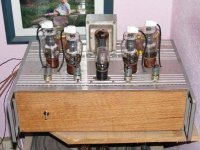
Shoog said:For all those lovers of amp porn heres a picture.
Ugly ain't it - you should see the insides
Shoog
fugly!


I know you had the teething troubles, but how would you rate the difficulty of build?
I would rate it as beyond basic, but not really any more difficult than the RLD which you have already mastered.
I just added a 120K load to the LL1517 input transformer and this seems to have tamed the strident top end I was experiencing. I may try triode strapping the 807's to see if it bring the gain down a little.
Shoog
Before you try triode mode on the outputs increase the value of the screen resistors on the input stage. Increasing the screen resistor value reduces the gain and linearizes the input stage. The Tabor rev. 3 schematic has ~10K on each screen. IIRC, the high screen value cut the gain and distortion of the input stage 50%.
I think what you are missing is that pentodes do not have lowest distortion with a fixed screen voltage. Look at the average transfer characteristics of the 6AU6-A comparing plate current to grid voltage or screen current to grid voltage for example (page 5 of the 1960 GE 6AU6-A data sheet ET-T916A, 4-60) . The average transfer characteristic is not a straight line but a curve. The curve gets steeper as the plate current increases. You will also note that the screen current tracks the plate current closely. By adding resistance to the screen you allow the screen voltage to drop as the plate current rises. This helps straighten the characteristic curve for lower distortion. The trade off is it also lowers the effective transconductance. This is another way of achieving lower distortion using local feedback on pentodes.
Roughly how many watts do you get?
Haven't really tested power output. I would estimate something like 20watts of class A. I'm going to put her back on the bench at the weekend to check for residual ringing. I'll see if I can push her to clipping. My speakers only need a few watts so its a bit of overkill really.
Shoog
Hi Shoog!
Congratulations on the job!
That is a real demonstration of rationality!
Congratulations on the job!
My speakers only need a few watts so its a bit of overkill really.
That is a real demonstration of rationality!
Hi Shoog,
Glad to hear the screen resistors helped.
Experiment 1: Increase the DC bias on the cathode bypass caps if the current voltage is not ~80% of voltage rating.
Looking at the cathode bypass caps- by their size, I'm guessing that the cathode bypass caps on the output stage are electrolytic. What is their voltage rating? At this time you only have 18V bias on the capacitors. If the voltage rating is 50 volts or higher you may want to increase the DC bias on the caps. The current 18V may be enough for 35V parts.
To increase the bias on the cathode bypass caps you could split R4 into a 2 resistor voltage divider then connect the end of R17 that is currently connected to ground to the middle of the new voltage divider. Adjust the resistor values to set the voltage on the bypass caps to ~80% of the rated voltage.
Experiment 2: Remove the need for cathode bypass caps.
Now that you have tried the higher screen resistance put a multi turn pot in the screen circuit like in the Tabor Rev. 3. This allows you to set the DC balance of the input stage. Balance the input stage while measuring the DC voltage between the cathodes of the output tubes. If you can set the amp up so that there is 0V DC between the cathodes and it seems stable you can put a jumper across the cathodes removing the cathode bypass caps from the circuit. Now you can hear what getting rid of the last capacitor in the signal path does for you.
Have fun!
I had her back on the bench. I had real difficulty getting a clear scope reading - there was all sort of wierd stuff going on with the signal. However I eventually established that there was still a resaponse peak centered around 50Khz. This is surprisingly noticable to the ear. I also did some listening tests and found that the bass was tight and punchy, but there was a definate suck out where the bass guitar should have been. I think there was a low frequency resonance which was picking up the lower bass but leaving a dip in the mid bass. Wierd sounding.
So today I changed out the LL1517 for the 110V:24V+24V toroidal transformer. I put a load resistor on the secondary of 120K. I didn't do any frequency sweeps but put her straight back into the main system. She sounds very similar to my DC7 amp (6080 PP with interstage toroidal transformer), but the top end is quite a bit more extended. She now has a very balanced sound with cymbals having real naturalness. Also the extra step down has put the gain into the right ball park for my system.
I am going to leave her at that for a while to see if anything subtle presents itself. Still I have a hunch I can put this one to bed now.
So I was thinking of trying my hand at a MOSFET based partial feedback amp with input and output transformers, as a way of utilizing the LL1517. Projects projects !!!
Shoog
Hi Shoog!
What happened with your input toroid transformer? Is it works good??
I am also looking for an input phase splitter transformer in 1:1+1 configuration.
I don't know what would be the optimal inductance for a line level transformer. May be 5H? It would be like the classical 600R imp. transformers.
Greets:
Tyimo
I used a step down ratio of about 5:1+1 using a small toroidal. I recently dropped the secondary load from about 14K to 1K as it was sounding a bit harsh. This smoothed things out a lot. Ringing is the real serious issue I have come up against when using toroidals as phase splitters. I think interwinding capacitance maybe an issue when trying 1:1+1, which will lead to roll off and peaking in response somewhere between 30-60K. If you can manage 2:1+1 then I would say you would have a better chance. Really its a suck it and see situation. Toroidals definitely do work though.
In a previous EL82 headphone amp I used microphone transformers from OEP for phase splitting. I had massive amounts of front end gain and these were configured as 9:1+1 - they sound absolutely fantastic.
Since then I have built another amp of almost the same design as the Tabor but used OEP transformers which are relatively cheap, sound sweet and can cope with 1:1+1 without issues. They are designed for 600R professional loads. I think I paid about €40.00 for a pair with screening cans.
Shoog
- Status
- This old topic is closed. If you want to reopen this topic, contact a moderator using the "Report Post" button.
- Home
- Amplifiers
- Tubes / Valves
- My Tabor Clone is finished.