I used IXY900 chips in the Tabor. I had real issues finding a CCS which was stable enough to withstand the power up spikes - the IXY900 was the only one which has been reliable. I have no zeners for protection in this one, but using zeners across the CCS should help.
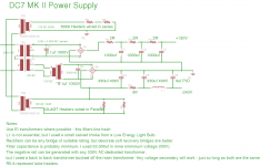
In the latest project which is update to the DC7 6080 amp I built, and which is based on the Tabor concept, I used a version of the LM317 with a voltage rating of 125V, this has worked flawlessly. I included 120V Zeners across them for protection.
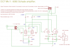
I can only really point you to my schematic for hints. The real issue with the Tabor is its relatively complex stacked power supply. I avoided this by using a +/- power supply off the single power transformer and hanging the front end off of the negative rail. All the usual complexities of this (ie biasing up the front end using voltage dividers and caps) is avoided by using the input transformer which is biased down to the grid voltage of the drivers. In the DC7 version I even managed to arrange the voltages such that the screens of the driver pentode were at 0V (effectively about +180V) which avoided the need for a seperate screen supply.
I have included the schematics of the DC7 Mk II because they represent the ultimate refinement of what I have worked on for the last 7yrs or so. Its quite simple but there are many hidden tricks. This would be a good one to attempt to copy or as a conceptual starting point.
Shoog
In the latest project which is update to the DC7 6080 amp I built, and which is based on the Tabor concept, I used a version of the LM317 with a voltage rating of 125V, this has worked flawlessly. I included 120V Zeners across them for protection.
I can only really point you to my schematic for hints. The real issue with the Tabor is its relatively complex stacked power supply. I avoided this by using a +/- power supply off the single power transformer and hanging the front end off of the negative rail. All the usual complexities of this (ie biasing up the front end using voltage dividers and caps) is avoided by using the input transformer which is biased down to the grid voltage of the drivers. In the DC7 version I even managed to arrange the voltages such that the screens of the driver pentode were at 0V (effectively about +180V) which avoided the need for a seperate screen supply.
I have included the schematics of the DC7 Mk II because they represent the ultimate refinement of what I have worked on for the last 7yrs or so. Its quite simple but there are many hidden tricks. This would be a good one to attempt to copy or as a conceptual starting point.
Shoog
Attachments
I use a single ended version of a Super Linear Cathode Follower as a preamp, so effectively a CF is the source. It has absolutely no issues driving the Toroidal phase splitter or the OEP's, and bass is in no way compromised. I think the reason is probably because the valve grids are such a slight load compared to the usual 600R input impedance these transformers are designed to cope with.
I would guess an anode follower might be a different question though.
Shoog
I would guess an anode follower might be a different question though.
Shoog
Unfortunately the last version I built I never got around to drawing up an accurate schematic for it. It uses two ECF80's per channel. There is an input pentode strapped as a triode, the output Cathode follower is direct coupled and sits on a pentode CCS. On the top is a sense triode which keeps the voltage over the CF constant at all times.
It looks and sounds very like a Aikido, but is based on the Vacuum State FVP5.
One day I will circuit trace it and put it up on the web somewhere.
Shoog
It looks and sounds very like a Aikido, but is based on the Vacuum State FVP5.
One day I will circuit trace it and put it up on the web somewhere.
Shoog
Could someone please guide me how to implement the design in post 1 with the DHT 1624 instead of the indirect heated 807. I am aware this will complicate the power supply regarding the filament supply where the goal of Shoog was to simplify. For such a re-design at least the following should be adressed, I think:
- Integrate the ccs in the filament heater. As the filament voltage is only 2.5V hum does not need to be an issue. Otherwise, four separate DHT-filament regulators (each with their own filament tap) of the design of Rod Coleman or Guido Tent for the 1624 can be applied.
- Whether the B+ can be used as is or should be adapted depends on if the operation point of a 1624 is different from a 807. Apart from that I notice that Gary applies a higher voltage in his design for the 1624 on his site, although it is not easy to determine exactly because of the cumulating voltages that allow for dc-coupling. Can you please elaborate on this?
- Status
- This old topic is closed. If you want to reopen this topic, contact a moderator using the "Report Post" button.
- Home
- Amplifiers
- Tubes / Valves
- My Tabor Clone is finished.