^^^^
White Paper by O. H. Schmitt, and personal experience from building two versions of the circuit. In both cases, the gain was half of what a single stage would give.
This also applies to the SS version.
White Paper by O. H. Schmitt, and personal experience from building two versions of the circuit. In both cases, the gain was half of what a single stage would give.
This also applies to the SS version.
Originally #21 posted by Miles Prower
^^^^
White Paper by O. H. Schmitt, and personal experience from building two versions of the circuit. In both cases, the gain was half of what a single stage would give.
This also applies to the SS version.
Hi Miles Prower,
Do I have to pay money to read it???
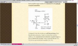
Here the asymmetrical cathode coupled is explained:
http://coupling-triode.blogspot.com/
hope it helps...
Kind regards,
Darius
I think the same papers are to be found at www.aikenamps.com/TI_Other.htm No matter what, you loose 6dB in a diff amp(or Schmitt-LTP).
Brgds
Lars
Brgds
Lars
#21 #23
Hi,
I can't find an asymmetrical cathode coupled amp there. ???
You don't loose 6dB, this is wrong.
This circuit is a special triode topology, don't look for SS=
solid state(?) examples.
Please read the text in the blog! I think books will not help
you. You don't have to pay or download something.
Kind regards,
Darius")
Hi,
I can't find an asymmetrical cathode coupled amp there. ???
You don't loose 6dB, this is wrong.
This circuit is a special triode topology, don't look for SS=
solid state(?) examples.
Please read the text in the blog! I think books will not help
you. You don't have to pay or download something.
Kind regards,
Darius
Had to do "your" circuit in spice and we are right in the middle.
If we do according to Schmitt and use anoderesistors on both stages we loose ca 6dB. But in this circuit the loss is 3dB compared to a standard triode gain stage.
Think I also saw this circuit in Bruce Bs "Audio Reality" where it is called "Grounded Grid Cascode Phono Preamp.
If we do according to Schmitt and use anoderesistors on both stages we loose ca 6dB. But in this circuit the loss is 3dB compared to a standard triode gain stage.
Think I also saw this circuit in Bruce Bs "Audio Reality" where it is called "Grounded Grid Cascode Phono Preamp.
cathode follower calculated...
Hello Lars,
yes, I know a lot of people who saw this circuit ...
of course in a symmetrical cathode coupled amp you loose 6dB.
But this is an asymmetrical one!
A grounded chathode stage and a grounded grid stage have the same
voltage gain number. The gain in the asymmetrical cathode coupled
stage is reduced by the cathode follower at the input.
Let us calculate the gain of the follower:
R load 8KΩll 22KΩ = 5900Ω, R follower 1/mutal cond. = 400Ω
5900Ω / (5900Ω+400Ω ) = 0,94 [gain reduce caused by load]
µ=100 1-1/100 = 0,99 [open output gain]
0,99 x 0,94 = 0,93 [this is the voltage gain of the cathode follower]
0,93 = -0,63dB
Thus the circuit loss is 0,63dB compared to a standard triode gain stage.
Where did you get 3dB from?
Kind regards,
Darius
Originally posted #25 by revintage
Had to do "your" circuit in spice and we are right in the middle.
If we do according to Schmitt and use anoderesistors on both stages we loose ca 6dB. But in this circuit the loss is 3dB compared to a standard triode gain stage.
Think I also saw this circuit in Bruce Bs "Audio Reality" where it is called "Grounded Grid Cascode Phono Preamp.
Hello Lars,
yes, I know a lot of people who saw this circuit ...
of course in a symmetrical cathode coupled amp you loose 6dB.
But this is an asymmetrical one!
A grounded chathode stage and a grounded grid stage have the same
voltage gain number. The gain in the asymmetrical cathode coupled
stage is reduced by the cathode follower at the input.
Let us calculate the gain of the follower:
R load 8KΩll 22KΩ = 5900Ω, R follower 1/mutal cond. = 400Ω
5900Ω / (5900Ω+400Ω ) = 0,94 [gain reduce caused by load]
µ=100 1-1/100 = 0,99 [open output gain]
0,99 x 0,94 = 0,93 [this is the voltage gain of the cathode follower]
0,93 = -0,63dB
Thus the circuit loss is 0,63dB compared to a standard triode gain stage.
Where did you get 3dB from?
Kind regards,
Darius
Attachments
Hello Darius,
To check I did a sim in LTSpice with your component-values. I did it at work and can publish it tomorrow. My guess is that there is some kind of feedback introduced at the grounded grid input. This might be less pronounced if you have a cascode as the secong stage.
Anyway will show it tomorrow.
Brgds
Lars
A grounded cathode stage and a grounded grid stage have the same voltage gain number
Sorry that is incorrect, the gain in a grounded grid amplifier is dependant on the source impedance of the preceding stage as the input impedance of a grounded grid amplifier is not infinite as it is in an ordinary cathode grounded stage. The gain of a grounded grid stage is:
gm*RL/1+RL/Rp+Zs(1/Rp+gm)
which can be compared to the gain in an ordinary cathode grounded stage which is gm*Rp*RL/RL+Rp.
As the grounded grid stage is driven by a cathode follower which has a non zero impedance the gain of the grounded grid stage will be less than what it would have been if it had been an ordinary cathode grounded stage,
The gain for "your" Asymmetrical cathode coupled amp is given in "Electrical engineers handbook" by Pender & McIlwain published 1936!
as gm^2*RL(RL+Rp)*[1+(Rp/Rk)+Rp*gm]/[2*(1+Rp*gm)+[RL+Rp)/Rk]+RL*[(1/Rp)+gm]]^2
I hope I copied that correctly!
You can't say that the gain of this stage is 3dB or some other fixed amount lower than an ordinary cathode grounded stage but it is for sure that the gain will be lower, due to the gain loss in the cathode follower and the loss due to non zero drive impedance to the grounded grid stage.
You can find analysis of most and every tubes stage someone ever thought about, you just need to know where to look!
Regards Hans
#29
Hello Hans,
in the future pelase tell the number of the treads you quoted from, thanks.
As posted in #24 these books will definitely not help you understanding.
A grounded cathode stage and a grounded grid stage have the same voltage gain number.
(Sorry but I don't care about 80 or 81, hi hi.)  Please note that gm (= s = mutal
conductance) is not the same for both triodes.
Kind regards,
Darius
Hello Hans,
in the future pelase tell the number of the treads you quoted from, thanks.
As posted in #24 these books will definitely not help you understanding.
A grounded cathode stage and a grounded grid stage have the same voltage gain number.
(Sorry but I don't care about 80 or 81,
hi hi.) Please note that gm (= s = mutal conductance) is not the same for both triodes.
Kind regards,
Darius
Hello Darius,
My guess from yesterday about feedback was right. This is also confirmed in tubetvrs post and some simming this morning. Simplified there is local feedback formed by the output impedance of the CF and the anoderesistor of the preceding stage. So my talk about 3dB or 6dB was wrong, it is componentvalue depending, sorry!
It will allways be a loss in the CF added to the feedback-loss(lower gain, better linearity and higher output impedance) from the next stage. So to minimize this one should use a high gm CF followed by, for example, a cascode.
Brgds
Lars
gain calculation explained
http://coupling-triode.blogspot.com/
Voltage gain calculation of the asymmetrical cathode follower
in three steps:
1. gain of the cathode follower:
Input resistance of the grounded grid stage is 8KΩ. This resistance is
parallel to R4 =22KΩ.
R load 8KΩ ll 22KΩ = 5900Ω
The output resistance of the follower is 1/mutal cond. = 400Ω
This value comes from the data book ECC83 2mA.
The output resistance of the follower and the load resistance are dividing
the no load output voltage of the cathode follower:
5900Ω / (5900Ω+400Ω ) = 0,94 [gain reduce caused by load]
The no load output voltage of the cathode follower is reduced by the amount
of signal voltage between grid and anode divided by µ. See triode transformer
mode. This is calculated by 1-1/µ [ECC83 µ=100]
1-1/100 = 0,99 [open output gain]
The no load gain multiplied by the gain reduce caused by the load gives the
gain of the cathode follower stage:
0,99 x 0,94 = 0,93 [this is the voltage gain of the cathode follower]
0,93
2.gain of the grounded grid stage:
The mutal conductance s is 0,5mA/V. This value comes from the data book.
The anode load resistance is 800KΩ it comes from the resistor multiplier
triode V3 of the SRPP arrangement. The no load resistance Ri at the anode is:
Ri = µ/s = µ x 2KΩ = 200KΩ . Both in parallel:
Ri ll Ra = 200KΩ ll 800KΩ = 160KΩ
The voltage gain is (Ri ll Ra) x s = 160KΩ x 0,5mA/V = 80
3.To get the total gain of the asymmetrical cathode follower the gain of the
cathode follower and the gain of the grounded grid must be multiplied:
vu = 0,93 x 80 = 74
[this is the voltage gain of the asymmetrical cathode follower amplifier]
74 = 37dB
Kind regards,
Darius
"Oldeurope" in answer to your post 30.
You still don't get it, the gain of a cathode coupled stage and a grounded grid stage is not the same as I explained in my post, this is well known and if you don't understand this you can look it up in any professional book about tube amplifiers. Please find out what the input impedance is for a grounded cathode and a grounded grid stage is and then you can start to understand how this affects the stage gain.
The book I refered to that was written in 1936 describe exactly the same circuit as you describe and give values for gain either for each part or for both tubes, (here they assume that both tubes are equal but the formula can easily be modified for a case with different tubes).
It is difficult to understand your comment
If you believe that you have invented a new circuit I must tell you that you are wrong, this circuit is very old and has been described in several classic tube books, do you just ignore all knowledge that is available from these classic works?
BTW your equation for gain of a cathode follower is also wrong, (hint, yours is too simplified).
Regards Hans
You still don't get it, the gain of a cathode coupled stage and a grounded grid stage is not the same as I explained in my post, this is well known and if you don't understand this you can look it up in any professional book about tube amplifiers. Please find out what the input impedance is for a grounded cathode and a grounded grid stage is and then you can start to understand how this affects the stage gain.
The book I refered to that was written in 1936 describe exactly the same circuit as you describe and give values for gain either for each part or for both tubes, (here they assume that both tubes are equal but the formula can easily be modified for a case with different tubes).
It is difficult to understand your comment
as the book I refer to describe exactly your circuit.As posted in #24 these books will definitely not help you understanding.
If you believe that you have invented a new circuit I must tell you that you are wrong, this circuit is very old and has been described in several classic tube books, do you just ignore all knowledge that is available from these classic works?
BTW your equation for gain of a cathode follower is also wrong, (hint, yours is too simplified).
Regards Hans
More about the grounded cathode - grounded grid amplifier.
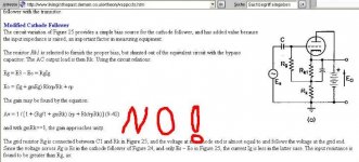
See here http://www.livinginthepast.demon.co.uk/vtheory/vappccts.htm down on the page "cathode coupled circuit" here a simplified formula for the gain is given and a statement which is of interest:
"The cathode-coupled amplifier behaves like a grounded-cathode stage having a valve of amplification factor m and an anode resistance greater than twice rp of one of the triodes" Meaning that the gain with any given load is lower than for the ordinary grounded cathode stage.
Regards Hans
#34
Hello Hans,
oh oh, your link does not look good
And I think it is the same with your books...
Darius
tubetvr said:More about the grounded cathode - grounded grid amplifier.
See here http://www.livinginthepast.demon.co.uk/vtheory/vappccts.htm down on the page "cathode coupled circuit" here a simplified formula for the gain is given and a statement which is of interest:
"The cathode-coupled amplifier behaves like a grounded-cathode stage having a valve of amplification factor m and an anode resistance greater than twice rp of one of the triodes" Meaning that the gain with any given load is lower than for the ordinary grounded cathode stage.
Regards Hans
Hello Hans,
oh oh, your link does not look good
And I think it is the same with your books
...Darius
Attachments
Hans: I see no wrong in simplifying some of the tube equations. IRL the spread af tube data have to much influence.
Darius:
In simple terms, you forgot point 4 where you should include the current feedback formed by the source impedance of the CF and the load of the second stage load!
Darius:
In simple terms, you forgot point 4 where you should include the current feedback formed by the source impedance of the CF and the load of the second stage load
!Originally #36 posted by revintage
Hans: I see no wrong in simplifying some of the tube equations. IRL the spread af tube data have to much influence.
Darius:
In simple terms, you forgot point 4 where you should include the current feedback formed by the source impedance of the CF and the load of the second stage load
Hello Lars,
this is done by calculating the cathode follower, see [gain reduce caused by load].
BTW: source impedance cathode follower is <400Ω
grounded grid input impedance is >8KΩ
Please note: If you take a pentode, Transistor, Cascode ...
the input impedance is only the mutal conductance of the
element. (Here 2KΩ ). In this case the loss caused by the current feedback formed by
the source impedance of the CF and the load of the second stage, means the loss
of the cathode follower caused by output voltage dividing, would be unacceptable.
This is why I wrote in post #24 that this is a special triode topology.
I need no cathode decoupling cap (LED etc.) and don't have its influence in sound.
thanks and
kind regards,
Darius
Oldeurope I must say that your way of argumentation is odd to say the least. I think the least you can do is to read what other people write, I wrote:
Regards Hans
Which you chose to ignore and copy what is written on the same page about "Modified cathode follower". If you scroll down a few lines on the same page you find Composite amplifiers which describe "cathode coupled circuit" and the cascode. You must be the only one who didn't found this on the page.See here http://www.livinginthepast.demon.co...ry/vappccts.htm down on the page "cathode coupled circuit"
Regards Hans
#38 I am sorry but...
Good evening Hans,
at first you have to learn how to calculate a cathode follower.
I explained it several times in this thread and in the blog but
you ignore it. Should I ignore your posts ?
D.
tubetvr said:Oldeurope I must say that your way of argumentation is odd to say the least. I think the least you can do is to read what other people write, I wrote:
Which you chose to ignore and copy what is written on the same page about "Modified cathode follower". If you scroll down a few lines on the same page you find Composite amplifiers which describe "cathode coupled circuit" and the cascode. You must be the only one who didn't found this on the page.
Regards Hans
Good evening Hans,
at first you have to learn how to calculate a cathode follower.
I explained it several times in this thread and in the blog but
you ignore it.
Should I ignore your posts ? D.
ReVintage,
I don't agree, one uncertainty is then added to a simplification which gives an even higher uncertainty about the end result, design is about predicting results by calculations and after measuring the end result also explaining any possible differences between theory and practice.
We can take a cathode follower as an example to show my point, if you calculate the output impedance of a high µ triode with the simplified formula that oldeurope gave us in this thread you get a result that is reasonably accurate, it is OK but still incorrect. However if you use the same formula for a low µ power triode as a 6C33C the result is very inaccurate. A 6C33C has a µ of typically 2.7 and a Rp of 80 ohm which gives a gm of 33.75mA/V, with the faulty formula this would give an output impedance of 1/gm which in this case is 29.6 Ω. If we instead use the correct formula Zo = 1/[(1/Rp)+gm] we get 21.6 Ω a 37% difference which can't be seen as insignificant.
The reason why I contributed in this thread is due to the obviously faulty statement that the gain in a cathode grounded stage and a grounded grid stage is the same which it is obviously not. even though the grounded grid stage is not use much in audio amplifiers it is for instance important to know the gain as the typical input for the feedback loop at the first stage cathode is a grounded grid stage from a gain point of view.
How should beginners in the tube hobby learn to do things if we spread inaccurate statements in a forum like this? All tube stages that have any practical use has already been analysed in detail many, many years ago and the literature is not so hard to find. Simplifications are useful but they don't give the exact knowledge that is possible to find and it is a risk that common simplifications is taken as the exact truth which could introduce problems in many cases.
Regards Hans
Hans: I see no wrong in simplifying some of the tube equations. IRL the spread af tube data have to much influence.
I don't agree, one uncertainty is then added to a simplification which gives an even higher uncertainty about the end result, design is about predicting results by calculations and after measuring the end result also explaining any possible differences between theory and practice.
We can take a cathode follower as an example to show my point, if you calculate the output impedance of a high µ triode with the simplified formula that oldeurope gave us in this thread you get a result that is reasonably accurate, it is OK but still incorrect. However if you use the same formula for a low µ power triode as a 6C33C the result is very inaccurate. A 6C33C has a µ of typically 2.7 and a Rp of 80 ohm which gives a gm of 33.75mA/V, with the faulty formula this would give an output impedance of 1/gm which in this case is 29.6 Ω. If we instead use the correct formula Zo = 1/[(1/Rp)+gm] we get 21.6 Ω a 37% difference which can't be seen as insignificant.
The reason why I contributed in this thread is due to the obviously faulty statement that the gain in a cathode grounded stage and a grounded grid stage is the same which it is obviously not. even though the grounded grid stage is not use much in audio amplifiers it is for instance important to know the gain as the typical input for the feedback loop at the first stage cathode is a grounded grid stage from a gain point of view.
How should beginners in the tube hobby learn to do things if we spread inaccurate statements in a forum like this? All tube stages that have any practical use has already been analysed in detail many, many years ago and the literature is not so hard to find. Simplifications are useful but they don't give the exact knowledge that is possible to find and it is a risk that common simplifications is taken as the exact truth which could introduce problems in many cases.
Regards Hans
- Status
- This old topic is closed. If you want to reopen this topic, contact a moderator using the "Report Post" button.
- Home
- Amplifiers
- Tubes / Valves
- cascode vs asymmetrical cathode coupled