This design seems to have three basic options:
1. Use resistor for biasing.
2. Use CCS with meager 4.5V drop across it.
3. Use CCS with 20-30V negative rail.
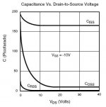
Capacitance of the DN2540 seems to run about 12pF at 20V, while at 5V it is much higher, near 50pF. So it would seem better performance is had with the negative rail (I'm being a little lazy here: don't want to install one).
I guess I'm interested in the sonic improvements moving from option 1 to option 3. What would you do ?
1. Use resistor for biasing.
2. Use CCS with meager 4.5V drop across it.
3. Use CCS with 20-30V negative rail.
Capacitance of the DN2540 seems to run about 12pF at 20V, while at 5V it is much higher, near 50pF. So it would seem better performance is had with the negative rail (I'm being a little lazy here: don't want to install one).
I guess I'm interested in the sonic improvements moving from option 1 to option 3. What would you do ?
Attachments
Got a little more context?
If the stage before it has differential output, you won't get a big benefit from the CCS. The negative rail is nice in that you can have grids at 0 volts and less capacitors, but the floating grids works well too like SY mentioned. Running at at 4-5 volts isn't recommended. Pic attached for others (I'm sure you saw or know this zigzagflux and SY )
)
If the stage before it has differential output, you won't get a big benefit from the CCS. The negative rail is nice in that you can have grids at 0 volts and less capacitors, but the floating grids works well too like SY mentioned. Running at at 4-5 volts isn't recommended. Pic attached for others (I'm sure you saw or know this zigzagflux and SY
)Attachments
SY said:Don't be afraid to cascode if you've got a negative rail.
Absolutely. If I have a negative rail, I WILL cascode.
And don't do a diff amp unless you either have a negative rail or are willing to put in the extra RC coupling it will take to float the stage up a few dozen volts.
Okay, that basically sums up my question- thanks.
Boris_The_Blade said:If the stage before it has differential output, you won't get a big benefit from the CCS.
Could you clarify? I have an input transformer/splitter, with the center tap to circuit common. That's about as differential an output as you can get.
the floating grids works well too like SY mentioned
So do you mean elevating the center tap of the transformer secondary to say 30V, thereby setting the grid to a static voltage? Then I would want to increase my B+ to compensate, correct? If that's the case, I would prefer the negative rail I suppose.
Hey flux,
If you have a transformer input, the best bet is just to go with a resistor tail instead of the CCS, and each leg of the transformer goes to a grid, and CT to ground. A CCS is used to enforce AC balanced voltage across the plate loads (when the loads are equal) where there is unbalanced AC input on the grids. Your transformer will already balanced, so the ccs will probably be unnecessary.
The attached pic is an example of a long-tail schmidt splitter where the grids are floating. (Also unnecessary in your case now)
Website where pic came from: http://www.bonavolta.ch/hobby/en/audio/split.htm
Attachments
Really ?!
I can't argue with the simplicity of a resistor, but doesn't the CCS aid in differences between triodes, CMRR, PSRR, and probably a few other things besides input balance?
Granted, I will have a shunt regulated 0D3 supply, so power supply ripple will be negligible, but something in my brain is not connecting with your statement.
- Status
- This old topic is closed. If you want to reopen this topic, contact a moderator using the "Report Post" button.
- Home
- Amplifiers
- Tubes / Valves
- Differential stage with CCS in cathode