Way to go Kirk!!!
You probably just have a defective EL84. The JJ's are now my favorite current production EL84. I had a quad in my Scott 222A, which after a short break-in period, sounded fantastic. (It too is cathode biased) They blow the Russian guys out of the water! If you don't want to do all the work that Ty recommends, just replace the 100 ohm cathode resistor to something like a 120 or 150 ohm, that will make them run much cooler. Just about all new tubes sound a bit thin at first. Get a replacement JJ, and give them another try. After a 50-100 hour break in, you will not be disappointed!
~~~~~~~~~~~~~John~~~~~~~~~~~~
kirk57 said:As mentioned, I bought all new tubes, the EL84s are JJs...
...when I use the EL84 in the socket for what I've been calling tube 1, it the plate gets cherry red and distorts, smells bad, etc. I tried it with several different EL-84s and the result is the same...
It doesn't sound like just one bad tube to me... it sounds like they all do it when put into socket 1.
Kirk - you're not mixing the old tubes with the new, are you?

Just to clarify, all the JJ EL84s have the same problem when plugged into that one socket, and none of the 6BQ5s do.
and yes, I had the three EL84 running with one 6BQ5 in the
1st socket, but not for long, and it seemed fine. I tried a lot of combinations trying to verify where the problem is...I thought they are equivalant?
I take it you are saying I should not do this?
and yes, I had the three EL84 running with one 6BQ5 in the
1st socket, but not for long, and it seemed fine. I tried a lot of combinations trying to verify where the problem is...I thought they are equivalant?
I take it you are saying I should not do this?
kirk57 said:yes, I had the three EL84 running with one 6BQ5 in the
1st socket, but not for long, and it seemed fine...
I take it you are saying I should not do this?
I'd say the likelihood of a mismatch is fairly high when mixing old tubes and new tubes. With the common cathode resistor, it's important that all four tubes match. As long as you don't see any cherry plates, the only thing that might suffer would be the quality of the sound.
Kirk,
If you're still having problems after you replace the cathode resistors, you may want to replace the 0.047 uF coupling caps between the phase inverter and output tube grids as well. I should have thought of this earlier, but you may have DC leaking through the caps, causing them to run way too hot.
If you're still having problems after you replace the cathode resistors, you may want to replace the 0.047 uF coupling caps between the phase inverter and output tube grids as well. I should have thought of this earlier, but you may have DC leaking through the caps, causing them to run way too hot.
kirk57 said:So I poked around and got the other readings:
EL84 (1)
pin 2 .065v
EL84 (2)
pin2 .007v
EL84 (3)
pin2 varies between -.001 and +.002v
EL84 (4)
pin2 .022v
It doesn't look like there is a whole lot of DC on the grids, but it certainly wouldn't hurt to take a second look. Output tube #1, which seems to be the one causing trouble, does have a slightly higher voltage on it than the others.
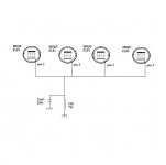
No, don't do it that way. Your goal here is to build four separate networks, one for each output tube. Each leg will have 30~35 mA running through it.
If you tie them all together, it's no different than what you had in the first place. One shared resistor with 120 mA could be the same as four separate resistors with 30 mA each, but only if all four output tubes are balanced and draw the same current.
If you tie them all together, it's no different than what you had in the first place. One shared resistor with 120 mA could be the same as four separate resistors with 30 mA each, but only if all four output tubes are balanced and draw the same current.
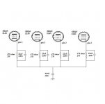
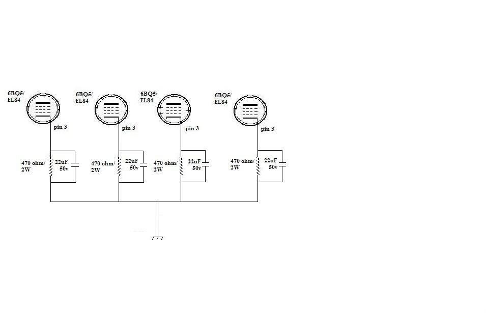
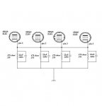
I replaced the single cap/resistor with 4 470 ohm/2 watts resistors bypassed with 22uF/25V caps.
I ran it connecting 8 ohm speakers to the 4 ohm taps (changed speakers and forgot about the difference)
It works, but the 470 ohm resistor connected to pin 3 of tube one is now burned, and looks like it took the capacitor (which is physically right next to it) with it.
Is this something that might happen using the wrong tap?
If so I'll just replace the R and C and try again.
Running your speakers on the wrong taps won't cause what you are seeing. Speaker impedances aren't constant anyway, they're a function of frequency. It is likely the impedance curve of your "8 ohm" speakers go all over the place. The tube which toasted the 470 ohm resistor is pulling too much current. I see that you say it is on socket #1, which was the one giving you problems before (post #56).
Those 470 ohm resistors absolutely should not be cooking. The tubes should be pulling 40 mA max through them. The resistor should be dropping no more than 20 volts. That's 0.8 watts across the resistor. They are rated for more than twice that (assuming you used the 2 watt parts). We need to figure out why that one tube (or the tube in that one socket) is pulling too much current.
Those 470 ohm resistors absolutely should not be cooking. The tubes should be pulling 40 mA max through them. The resistor should be dropping no more than 20 volts. That's 0.8 watts across the resistor. They are rated for more than twice that (assuming you used the 2 watt parts). We need to figure out why that one tube (or the tube in that one socket) is pulling too much current.
Which capacitor are we talking about, the smaller disk caps on the preamp/phase splitter or the larger .047uF ones connected to
pin 3 of the other output tubes, but to pin 1 of this one (this tube is wired differently than the other for some reason)
how do I determine the socket is bad?
pin 3 of the other output tubes, but to pin 1 of this one (this tube is wired differently than the other for some reason)
how do I determine the socket is bad?
kirk57 said:Which capacitor are we talking about, the smaller disk caps on the preamp/phase splitter or the larger .047uF ones connected to
pin 3 of the other output tubes, but to pin 1 of this one (this tube is wired differently than the other for some reason)
how do I determine the socket is bad?
Something badly amiss here, it should be wired the same as all the others - incidentally pin 1 is no connection on a 6BQ5/EL84 so if this is where the grid resistor and coupling cap are connected this is the reason why you are having problems with this tube - should be connected to pin 2. Big Oops if true...

Pin 3 is the cathode and this is where the 470 ohm resistor and 22uF cap go.. 4 and 5 are filament, 6 do NOT use, 7 is plate, 8 do NOT use, 9 is the screen grid.
- Status
- This old topic is closed. If you want to reopen this topic, contact a moderator using the "Report Post" button.
- Home
- Amplifiers
- Tubes / Valves
- Very low output from Knight KN928 amp