Family_Dog said:Hi Jojo,
Glad you were able to sort out the problem. I think it would be wise to use closer-matched cathode resistors of 470 ohms each, you would require at least 3W ratings. Other than that, you seem to be on top of things!
Enjoy your amplifier!
-Eric
Hi Eric,
I thought so too, will do that by next week once I get the chance to match up some resistors. Good thing the owner of the parts store is a friend of mine and let's me pick and match the parts that I need. I was surprised to find that this amp uses 10W rating for it's cathode resistors.

Thanks!
JojoD
Hi Jojo,
Nothing wrong with the 10W resistors, at least the chance of them burning out is virtually negligible. Currently, I use 3W resistors in my amplifiers and have had no problems, but I am intending to upgrade to a higher wattage as soon as I get to a parts store.
Have you considered fitting some sort of series resistor between the HT+ windings of the transformer and the rectifier anodes? Any valve needs some sort of series resistance and it would take some of the strain off your power supply components at switch on. Here you would be wise to use 10W rated components as well.
Have you got a picture of your completed amplifier? Post it, I always like looking at various Mullard amplifiers.
-Eric
Family_Dog said:Hi Jojo,
Nothing wrong with the 10W resistors, at least the chance of them burning out is virtually negligible. Currently, I use 3W resistors in my amplifiers and have had no problems, but I am intending to upgrade to a higher wattage as soon as I get to a parts store.
Have you considered fitting some sort of series resistor between the HT+ windings of the transformer and the rectifier anodes? Any valve needs some sort of series resistance and it would take some of the strain off your power supply components at switch on. Here you would be wise to use 10W rated components as well.
Have you got a picture of your completed amplifier? Post it, I always like looking at various Mullard amplifiers.
-Eric
Hi Eric,
Once I have the time again, I will be implementing a series resistance in the HT. I noticed though that when using a 5U4G the HT rises fast after switch on up to 480V then down to 400V while a 5AR4 takes about 5-8 seconds before the HT starts to rise and will stop rising at about 420-425V. Kinda weird since I though tube rectifiers are all slow ramping. I like the 5AR4 better.
Anyways, at the request of it's owner, I cannot post any pics.
Hi Jojo,
It's a pity that the owner is shy about a picture, but none the less...
The 5U4G has a heater only, without the need to first warm up a cathode, whereas the 5AR4 has a cathode element which has to be "warmed up" by the filament, hence the delay.
Use the 5AR4 in preference to the 5U4G, for a "gentler" warm up of HT, and also because its filament current is 1 amp less than the 5U4G, which places less of a load on the mains transformer.
-Eric
SY said:Take a look at how each tube implements its emissive cathode and the differences in warmup time will become clear.
Thanks for the heads up! This is what I like about tubes... always something new to learn.
Family_Dog said:Hi Jojo,
It's a pity that the owner is shy about a picture, but none the less...
The 5U4G has a heater only, without the need to first warm up a cathode, whereas the 5AR4 has a cathode element which has to be "warmed up" by the filament, hence the delay.
Use the 5AR4 in preference to the 5U4G, for a "gentler" warm up of HT, and also because its filament current is 1 amp less than the 5U4G, which places less of a load on the mains transformer.
-Eric
Hello Eric,
The difference between the 5AR4 and 5U4G prompted me to read my brother's trusty (and veeery old) RCA tube manual. I kinda like the way the 5AR4 ramps up it's voltage, makes me feel safe as my filter caps are within their safe working voltage. Well, as long as the voltage doesn't exceed my caps' ratings I guess.
JojoD
Mullard 5-20 : Episode II - Return of the trafo's
Just over 2 years ago I started this project and thread. At that time I eventually got them working but not to the specs of the Claus Byrith re-design (which was my final goal).
I now got the correct transformer and chokes and re-build them again, also using matched Svetlana El34's , Auricaps and Riken Ohm carbon resistors (looks and sounds beautifull - those Rikens )
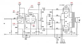
Accordng to Mr. Byriths design notes, you should get certain vlotages at certain points. Although I had the HT transformer made according to spec. , I get a little more out of it - HT.
My measured values differ now from the specified values, and I want to know if I must adjust resistors, or are my values acceptable? I also did order the Morgan Jones 3rd edition on Valve Amplifiers, so should be able to answer these questions myself within the next month or two
After these "expensive" mods. I must say, it was worth every $. Get almost 40W out of each, sound improved on all areas, bass, clarity, soundstage, imaging - just wonderfull, also virtually no humm : 1.4mV on scope.
Measurements:
Just over 2 years ago I started this project and thread. At that time I eventually got them working but not to the specs of the Claus Byrith re-design (which was my final goal).
I now got the correct transformer and chokes and re-build them again, also using matched Svetlana El34's , Auricaps and Riken Ohm carbon resistors (looks and sounds beautifull - those Rikens
)Accordng to Mr. Byriths design notes, you should get certain vlotages at certain points. Although I had the HT transformer made according to spec. , I get a little more out of it - HT.
My measured values differ now from the specified values, and I want to know if I must adjust resistors, or are my values acceptable? I also did order the Morgan Jones 3rd edition on Valve Amplifiers, so should be able to answer these questions myself within the next month or two
After these "expensive" mods. I must say, it was worth every $. Get almost 40W out of each, sound improved on all areas, bass, clarity, soundstage, imaging - just wonderfull, also virtually no humm : 1.4mV on scope.
Measurements:
Attachments
Hi JdeV,
Congrats on your "remake"! It is fun doing this. My 5-20s all use the Byrith front end (I did not require all the gain that the EF86 offered in pentode mode) but I still use Cathode Bias. At some time in the future, I might - or might not - fit a separate Bias transformer for the output valves, as my original Mains transformers don't have a suitable tapping for this.
Your voltages are not too far out of spec, in fact they are pretty good. However, there are a copuple of points you can look at:
Check the voltage of your AC supply. We used to have a nominal 220V supply here, but this has been upped to 240V to confirm with EC standards. I have on occasion measured 247VAC mains, which is a bit high for my liking. Move the Mains Input of your transformer to a 250v tap (if you have one) and see how this affects your HT. The difference it might have on your LT filament windings is negligible.
If your voltages are still high, insert a wire-wound resistor between each secondary tapping of your HT transformer windings and the rectifier. You can work out the value by taking the nominal current value and applying Ohm's Law, but it probably would not be more than 100 ohms or so. Remember to allow for a suitable wattage, those resistors can get hot!
-Eric
You make me green with envy! Here in Indonesia, on the island of Java, our nominal mains voltage is 220 but it usually measures 10% - 15% low. Most, if not all, of the losses are in the distribution network. Trying to get it seen to is like pulling teeth.Check the voltage of your AC supply. We used to have a nominal 220V supply here, but this has been upped to 240V to confirm with EC standards.
Hi Ray!
Well, it has it's drawbacks... I seem to have replaced so many light bulbs that are supposed to be rated for 250V since they've upped the national grid. Changed three globes just last week!
But I do remember when I first bought this house, some 30 years ago, that I had AC mains readings as low as 190V during winter. Since they built the new power station though, that is something of the past.
I seem to recall you were also building or repairing 5-20s... or am I thinking of someone else?
-Eric
No, it wasn't me working on 5-20s. However, I am thinking of building an amp with similar topology but using a 6AU6 as the input pentode stage, a 6SL7 splitter with another 6AU6 as a CCS for the tail, and a pair of EL34s in pentode mode (not UL). I hope the high gain from the pentode input stage, which would be too much for the 5-20 with its UL output stage, should enable me to add enough NFB for a decent damping factor, even with a straight pentode PP ouput stage. I'll also probably include a step network in place of the coupling capacitors between the splitter and the OP tubes, to improve LF phase margin, and use fixed bias. What do you think?
Speaking of the weather in sunny South Africa, it's been unseasonally rainy here in Indonesia since the supposed start of the dry season (May-October, same as northern Australia). Maybe this is a year of el niño?
Speaking of the weather in sunny South Africa, it's been unseasonally rainy here in Indonesia since the supposed start of the dry season (May-October, same as northern Australia). Maybe this is a year of el niño?
Re: Mullard 5-20 : Episode II - Return of the trafo's
After rolling some tubes today, I noticed with some of the older tubes, (for EF86), the voltages are spot on - as specified. So with time the new tubes I am currently using will also give the same voltages.
Just finished a listening session with another hi-fi fanatic and just can not believe the quality of the sound from these amps, truly amasing. My next surprise (pray it will be) is the Seas Thor TL speakers I am bussy building. Hope they do justice to the amps. Will find out within the next week or 2.
Just for the fun, a pic or 2:
Introducing..... the all new super duper Mullard designed, Byrith modified.... EL34 35W monoblock.
JDeV said:Accordng to Mr. Byriths design notes, you should get certain vlotages at certain points. Although I had the HT transformer made according to spec. , I get a little more out of it - HT.
My measured values differ now from the specified values, and I want to know if I must adjust resistors, or are my values acceptable?
After rolling some tubes today, I noticed with some of the older tubes, (for EF86), the voltages are spot on - as specified. So with time the new tubes I am currently using will also give the same voltages.
Just finished a listening session with another hi-fi fanatic and just can not believe the quality of the sound from these amps, truly amasing. My next surprise (pray it will be) is the Seas Thor TL speakers I am bussy building. Hope they do justice to the amps. Will find out within the next week or 2.
Just for the fun, a pic or 2:
Introducing..... the all new super duper Mullard designed, Byrith modified.... EL34 35W monoblock.
Attachments
Suggested tubes
I eventually got the perfect speakers for my Mullards. I build the 'BIB' with Fostex FE207E fullrange drivers. Only one word: WOW!!
This is my definition of Hi-Fi, everything is just perfect, base, mids, highs - it's all exactly how it should be - for my ears ;-)
I now want to replace the tubes, what are the latest, best EL34's, EF86 and ECC83 / 12AX7's recommended for this application?
Thanx for all replies.
And it's belly:
Mullard!
Don't laugh - a few years ago I GAVE AWAY 20 x brand new boxed Mullard EL34 tubes, thinking I would have no further use for them. I kept only six, all of which are currently in use.
Heart-breaking, ain't it?
-F_D
Mullard!
Don't laugh - a few years ago I GAVE AWAY 20 x brand new boxed Mullard EL34 tubes, thinking I would have no further use for them. I kept only six, all of which are currently in use.
Heart-breaking, ain't it?
-F_D
Eric, you should be "named and shamed" for doing that

- Status
- This old topic is closed. If you want to reopen this topic, contact a moderator using the "Report Post" button.
- Home
- Amplifiers
- Tubes / Valves
- Mullard 5-20