So the setup I'm liking adds an additional Obbligato 70 uF film/oil capacitor to the previous 47 uF Obbligato film and 70 uF film/oil. This Configuration Y seems to retain the goodness of the pure film cap added to the film oil.
I actually tried this previously, but thought it a bit too dark sounding. But full disclosure - I made some other changes to the system recently - upgraded to Schottkys on the DAC, freed DAC from steel case, speaker wire tweaking, spanking new bypass caps on the amp, and I think those changes changed the tonal balance upwards slightly. I've been trying to avoid changing other parts of the system in general while I work on this project to avoid a moving target (except for trying different amps so that the result isn't tied to sounding good with a single amp). Moral of the story - it's probably worth trying different combos of last PSU cap to fine tune the tone.
Next up is trying a "PDM Style" power supply. I wasn't originally going to do this, but after the various discussions in this thread and a recent thread over at Audioasylum where some mentioned preferring the configuration, it seemed worth spending the 28 bucks for another Hammond 2H choke.
A Pseudo Dual Mono supply in my case will split off the last LC cells such that each channel has it's own final LC cell:
........... ==== LC
CLC ==|
........... ==== LC
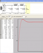
Here is the PSUD impulse graphic for Configuration Y, my current favorite, which is a stereo supply. The larger capacitance helps noise slightly too. I'll compare it to a few PDM configurations next:
I actually tried this previously, but thought it a bit too dark sounding. But full disclosure - I made some other changes to the system recently - upgraded to Schottkys on the DAC, freed DAC from steel case, speaker wire tweaking, spanking new bypass caps on the amp, and I think those changes changed the tonal balance upwards slightly. I've been trying to avoid changing other parts of the system in general while I work on this project to avoid a moving target (except for trying different amps so that the result isn't tied to sounding good with a single amp). Moral of the story - it's probably worth trying different combos of last PSU cap to fine tune the tone.
Next up is trying a "PDM Style" power supply. I wasn't originally going to do this, but after the various discussions in this thread and a recent thread over at Audioasylum where some mentioned preferring the configuration, it seemed worth spending the 28 bucks for another Hammond 2H choke.
A Pseudo Dual Mono supply in my case will split off the last LC cells such that each channel has it's own final LC cell:
........... ==== LC
CLC ==|
........... ==== LC
Here is the PSUD impulse graphic for Configuration Y, my current favorite, which is a stereo supply. The larger capacitance helps noise slightly too. I'll compare it to a few PDM configurations next:
Attachments
I've been running with the "PDM Style" split supply since my post last fall and I prefer it. Any concerns about interaction resonances using an additional choke were dissipated once I heard the new supply. It does sound more damped, more solid than the single LCLC.
Next, I finally tried the Cree silicon carbide diodes I got at the beginning of the project. I replaced the Mullard GZ32/GZ34 supply with two 1200v 5a Crees in full wave center tapped mode. I was surprised and pleased at the healthy improvement over tube rectification in this circuit, for my taste. Treble and tone improved the most.
Choke input, Crees, Paper-in-oil caps: yumm.
As a bonus, the smaller rectification footprint makes up somewhat for the "whole lotta caps" sprawl in the PDM Style supply.
The next step in the project, as planned, will be to try the LC->Swenson/Pimm regulator configuration and compare it to the SS rectified PDM Style LCLC supply. Gary Pimm was able to continue working on his regulator project over the holidays, and has recently updated his Swenson Regulator page.
Gary was good enough to provide a BOM and PCB layout file on his download page.
Gary Pimm's ExpressPCB boards arrived and they look good. The three mini boards each contain two regulator circuits. That is 60 bucks for six regulators - a good deal, methinks. Fast delivery too: the boards were ordered Tuesday night and they arrived Friday morning.
I'm not sure exactly how the heatsinking will work yet. I need to get the parts in hand and see how they fit on the boards and into a potential chassis. I'll probably just kludge something up to start.
A potentiometer is provided on the circuit to adjust the output voltage. I asked Gary about the proper sizing of the pot. Here is his response:
*******************
The size of the pot controls how much adjustment range you will have. The reference CCS (Q3,Q4) sources ~350ua. This current through R10 and R11 determines the output voltage. A 100K pot gives ~35 volts of adjustment (.00035*100000)where a 50K pot gives ~17.5 volts adjustment (.00035*50000). The 270K resistor drops ~94.5 volts (.00035*270000).
So with the 270Kresistor + the 100K pot the output voltage range should be ~95v to 128v. You should choose R11 based on how much adjustment range you want. To choose R10 use the output voltage you want divided by .00035 (350ua) to come up with the total resistance needed. Now, subtract half the value of R11 from this number. This should get you to the output voltage you want with R11 close to center.
Example:
We want 150 volts out with a range of +/- 6 volts.
Total resistance = 150/.00035 = 428K
a 50K pot should give ~+/-8.75 volts range.
R10 = 428K-1/2(50K) = 428K - 25K = 403K
390K is the nearest standard value for 5% parts. This would give a range of 136.5v to 154v
Using 390K + 13K resistors for R10 would shift the range up by 4.5 volts to 141 to 158.5v.
Remember that the reference CCS will vary from part to part so you will need to change the reference current in the calculations. Q3 determines what the bias CCS will source.
For simplicity using the 100K pot will cover a wide range of part dependent variables.
In my bench power supply I have a 500K pot for R11 and an 82K resistor for R10. The range on this supply is ~40v to 215v.
- Status
- This old topic is closed. If you want to reopen this topic, contact a moderator using the "Report Post" button.