G said:The current draw will be 5mA per side and since it is a class A there is not going to be much variation in the load.
Would you be interested in an independent shunt regulated supply for each side? It is certainly an upgrade, but does consume more DC current since you need to drive two VR tubes instead of just one.
zigzagflux said:
Would you be interested in an independent shunt regulated supply for each side? It is certainly an upgrade, but does consume more DC current since you need to drive two VR tubes instead of just one.
Sure. I would be interested. About the supply you designed. I can use a transformer with a higher voltage rating and use more RC sections hence more filtering before the VR tube. I will draw up the schematic for the preamp when I get back from physical therapy. I'm currently recovering from a broken leg. I don't mind elaborate designs so don't hold back on my part.
G said:I don't mind elaborate designs so don't hold back on my part.
Hope the leg heals well. I certainly won't hold back on the design. The beauty of this method, IMO, is that lots of filtering prior to the CCS is completely unnecessary. Less truly is more, in this case. I would not recommend additional RC sections, as they will do nothing to improve the very low ripple present across your VR tube. They may even add to instability, so I would leave this simple topology as is, and only play around with the values.
It sounds like you haven't purchased any parts yet? If so, I would suggest the following modifications:
Increase the transformer voltage and current. Maybe a Hammond 363CX or better (don't know if you need the 6.3V windings for your 6SN7's). Regardless, a little more voltage will help with flexibility, and more current is always a good thing. But we may get this one to work as specified. To be honest, I'm not a huge fan of Hammond iron; it throws out a lot of audible and magnetic hum that messes with my audio xfmrs. Frustrating.
Definitely go with separate CCS and VR tube for left and right channels. Minimum of 10mA through the VR, but no need to go up to 20mA. Eases the requirements of the rest of the power supply.
Once you get this far, and determine what xfmr you go with, we can discuss stability. As a precursor, it looks to me like 3.3uF for C1 and 27uF for C2 is a great combination. But based on the potential changes above, these values will be refigured.
So you are wanting to use a single power transformer with a separate choke and VR tube per channel correct? I have a rather large potted transformer that I could use although the voltage is 300 - 0 - 300 @150mA. Just slight overkill there. What do you think? I even have 4 40uF motor run caps, along with the afore mentioned transformer, that I have been saving for a 2A3 amplifier that I may or may not build one day. I also have 2 20H chokes(Hammond) rated at 100mA with a DCR of 181 ohms. BTW thank you for for your comment about the leg. It is healing fine. It's just taking it's sweet time about it.
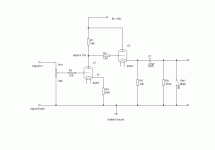
BTW here is the preamp circuit. Pretty simple and to the point. I kept the voltages low so that I did not need to use a seperate filament winding for each stage. I can bias the filaments to 80v or so and still be within the 6SN7s specs for heater above cathode voltage.
Attachments
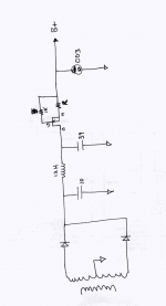
I would propose one power transformer, one choke, two CCS, two VR tubes.
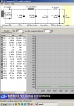
Here's what I came up with. In order to get some control of the amount of distortion on the secondary voltage, I reduced the VR current to 13mA, which is still a good number.
How's that look to you? It's tight, but it works.
Here's what I came up with. In order to get some control of the amount of distortion on the secondary voltage, I reduced the VR current to 13mA, which is still a good number.
How's that look to you? It's tight, but it works.
Attachments
zigzagflux said:I would propose one power transformer, one choke, two CCS, two VR tubes.
Here's what I came up with. In order to get some control of the amount of distortion on the secondary voltage, I reduced the VR current to 13mA, which is still a good number.
How's that look to you? It's tight, but it works.
What are you referring to when you say CCS. I have a couple of the IXYS current regulators you spoke of.
G said:What are the specs of the power tranformer? Is it still the 396BX? The results certainly look good.
The 369BX, yes. Things are tight, but it should work. In my experience, Hammonds are marginally rated, but you should be fine. Ideally, you want to measure the xfmr parameters before buying the capacitors, in case slight tweaks are necessary. Fortunately, the sizes of the capacitors are small enough that you could afford metallized film throughout (or maybe use one of those 40uF motor runs).
G said:What are you referring to when you say CCS. I have a couple of the IXYS current regulators you spoke of.
Niiice. I use them myself. CCS=Constant Current Source. Subjectively, the IXYS work better in power supply applications than the DN2540, though I'm sure many will disagree. I also prefer the single device CCS over the cascoded in power supplies. Again, I may be alone in this opinion.
zigzagflux said:
The 369BX, yes. Things are tight, but it should work. In my experience, Hammonds are marginally rated, but you should be fine. Ideally, you want to measure the xfmr parameters before buying the capacitors, in case slight tweaks are necessary. Fortunately, the sizes of the capacitors are small enough that you could afford metallized film throughout (or maybe use one of those 40uF motor runs).
Niiice. I use them myself. CCS=Constant Current Source. Subjectively, the IXYS work better in power supply applications than the DN2540, though I'm sure many will disagree. I also prefer the single device CCS over the cascoded in power supplies. Again, I may be alone in this opinion.
I don't suppose you could draw out a shematic of the proposed supply could you? I'm not quite sure how to utilize the IXYS current regulator. Do I put it in series with the OD3 or in parralel with it?
Not sure if I understand. Are you talking about the resistor in my latest schematic, tucked up against the source of the FET? This is chosen based on the total current I want to provide (23mA). I select it as an approximation based on the datasheet:
http://ixdev.ixys.com/DataSheet/98704.pdf
This gets you close, but you would really want to test for the optimal value.
There's a few threads on this and the DN2540 you could check out. They really do work well.
http://ixdev.ixys.com/DataSheet/98704.pdf
This gets you close, but you would really want to test for the optimal value.
There's a few threads on this and the DN2540 you could check out. They really do work well.

- Status
- This old topic is closed. If you want to reopen this topic, contact a moderator using the "Report Post" button.
- Home
- Amplifiers
- Tubes / Valves
- Choke loaded PSU versus VR tube regulated PSU?