In my version a current source shoulder is biased from triode's cathode so it always mimic an average current, though it does not save from transients (phase delay on averaging!) that anyway mimics a SE signature so may be not a big deal (let's breadboard and see). Also, I'm going to implement combined PFB by current and NFB by voltage. Bias for a tube will be stabilized by one transistor.
Ok Gentlemen;
I've started a new thread:
http://www.diyaudio.com/forums/showthread.php?postid=1446793#post1446793
Questions/suggestions/objections welcome!")


I've started a new thread:
http://www.diyaudio.com/forums/showthread.php?postid=1446793#post1446793
Questions/suggestions/objections welcome!
smoking-amp said:Re: Michael
"Sounds like you're suggesting splitting the difference ..."
Yes.
Although, on thinking about this again, I think I may see an elegant solution (at least for the CCS'd LTP version). All one needs is an appropriate resistance added across the tail CCS to track the increased current needs with increasing signal (due to dist.).
This strikes me as being related to the WE harmonic equalizer (HE) scheme. Just put in a tail resistance that nulls the 3rd harmonic dist. So simple. Why didn't I think of that before.
The high Gm of the Mosfet will keep tail voltage variation small, so it will require a lower value tail resistance than for P-P tubes HE. Unfortunately, this will attenuate the AC complementary current too. So maybe use something more like a gyrator circuit (inductor emulation). Probably can do this with just modifying the CCS tail circuit. Or just use a real inductor for the tail.
Don
I thought the HE was a feedback scheme based on feeding the AC distortion signal from the B+ (depending on >0 dynamic impedance in the B+ supply) to the cathodes i.e. the f3 current signal tapped from the B+ will add to the grid-cathode signal and cancel some of the f3 voltage. I guess it's a sort of positive current feedback to voltage. (that sounds strangely familiar...)
This scheme would act in reverse, sensing the distortion current from the cathode (I can add a common cathode resistor to my circuit) and AC couple it into the control loop (somehow) such that the MOSFET tracks the f3 current. I think I'm following you but still not sure how the circuit could be arranged in the servo case.
In general, connecting resistance in parallel with the CCS will reduce the f3 but I don't have a feel for the ratios. Needs more thought but sounds promising.
Michael
Re: Re: Throwing in my hat too
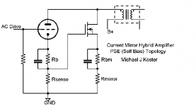
Top OP-FET exactly mirrors the top tube current X3 .
Basically three fake tubes in parallel with one real one = 4.
Bottom OP-FET fakes 4 SEPP anti-Tube mirrors, and servos
out any long time constant DC.
The plate of the reference tube should see 1/8 of the real
load, and behave just as 8 perfectly matched parallel tubes
might in a "normal" SE configuration. In theory that is....
I wish to avoid completely isolating the tube from the real
load in any manner that dumbs it down to a tube pre-amp
with a solid state final.
Wavebourn said:
Interesting...
What's for the transistor in parallel with the tube?
Top OP-FET exactly mirrors the top tube current X3 .
Basically three fake tubes in parallel with one real one = 4.
Bottom OP-FET fakes 4 SEPP anti-Tube mirrors, and servos
out any long time constant DC.
The plate of the reference tube should see 1/8 of the real
load, and behave just as 8 perfectly matched parallel tubes
might in a "normal" SE configuration. In theory that is....
I wish to avoid completely isolating the tube from the real
load in any manner that dumbs it down to a tube pre-amp
with a solid state final.
Re: Kenpeter
"The plate of the reference tube should see 1/8 of the real
load, and behave just as 8 perfectly matched parallel tubes
might in a "normal" SE configuration."
This lighten the load on the triode approach should allow the scheme to perform better than real SETs in terms of a more constant tube Mu. Some listening tests will be required though to determine whether this succeeds in terms of SET sound satisfaction or just makes a lower distortion amplifier. The same issue applies with Anatoliy's scheme.
Re: Michael
"I thought the HE was a feedback scheme based on feeding the AC distortion signal from the B+ (depending on >0 dynamic impedance in the B+ supply) to the cathodes i.e. the f3 current signal tapped from the B+ will add to the grid-cathode signal and cancel some of the f3 voltage."
This Harmonic Equalizer scheme seems to show up in several forms and I haven't seen a really coherent explanation for them.
The WE/Kreer patent (1,970,325) has the resistor in the B+, but the WE92A amplifier that references the patent has the resistor in the cathode circuit. Kiebert in "System Design Factors for Audio Amplifiers" has the resistor in the cathode circuit too.
At least they are sensing the same current in both places, and both act to reduce gain with increased common mode current (well, for a triode anyway). The cathode position would seem to have greater feedback effect, so should waste less B+ power with a smaller resistor I guess. But the grid coupling cap for the cathode position (WE92A) seems to cause biasing problems for class B operation apparently.
One thing that puzzles me is that this grid coupling cap (WE92A) appears to knock out most of the CM feedback effect at the grid, returning the scheme back to just the mere plate voltage reduction scheme the B+ resistor uses. When I look at the HE scheme in terms of time domain gain compensation, rather than frequency domain mixing, things look a bit different. Some improvements on the WE scheme seem likely.
Don
smoking-amp said:Re: Kenpeter
"The plate of the reference tube should see 1/8 of the real
load, and behave just as 8 perfectly matched parallel tubes
might in a "normal" SE configuration."
This lighten the load on the triode approach should allow the scheme to perform better than real SETs in terms of a more constant tube Mu. Some listening tests will be required though to determine whether this succeeds in terms of SET sound satisfaction or just makes a lower distortion amplifier. The same issue applies with Anatoliy's scheme.
The load isn't "lightened" with the right matching Xformer,
and a load that will use the extra power to good purpose.
All the virtual tube drains react just as the real plate to the
load. The virtual tubes are never intended to carry an unfair
share that might relieve the reference tube of a reference
burden.
It should never be any more linear than 8 identical tubes in
parallel. For any given Watt SE output, perhaps 8 tubes are
more linear than a single tube, but thats not unreasonable.
I went to a lot of trouble to keep the SE tube reality check
intact. The only thing certain not to sound SE is the PP iron.
As long as the OpAmps have sufficient rail headroom...
FETs will be expected to duplicate and multiply any cathode
current transient from Cutoff to A2 Saturation up to 20KHz.
Thats a tall order for gate drive....
kenpeter said:
As long as the OpAmps have sufficient rail headroom...
FETs will be expected to duplicate and multiply any cathode
current transient from Cutoff to A2 Saturation up to 20KHz.
Thats a tall order for gate drive....
I actually am using both sections of a TL083 in parallel for the gate drive. I don't think the source-gate voltage swings much though. I'll try the 10 kHz square wave test tomorrow.
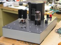
I've been listening to my new amp all night and I must say subject to the 4 watt power output and my 93db/w speaker (mono JBL4312 as I just built one amp) it sounds good. I was worried about the MOSFET because the heatsink gets quite hot but I wanted to keep listening even if it blew up...
The harmonic signature is definitely there; I played with different transformer taps to change the load line and like the 5ohm tap (I think my speaker is 6 ohms in some frequency range, even though it's 8 ohms nominal.
I liked Diana Krall and Commander Cody the best (probably because they are the best quality recordings of the ones I tried) I'll need to dig up a Steely Dan for the next session. If I keep building these amps I'm going to need to replace my music collection with more hi fi recordings.
I think it sounds good enough to be worth making another one or even a pair using a good linear triode like a 2a3 or a type 45.
Michael
Attachments
"The load isn't "lightened" with the right matching Xformer,
and a load that will use the extra power to good purpose."
Yes, for sure. I was just highlighting the option Michael, Ken, and to some extent Anatoliy each have available with your respective designs, with N times power multiplier capability.
My CCS'd LTP design, the one I actually built, is constrained to only 2X power boost thus far, so is less flexible in this respect. Since lightening the tube load, via xfmr primary Z increase, reduces power output.
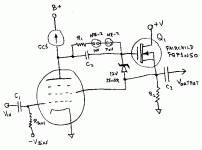
I do have another "trick" up the sleeve here though for the triode side. See attached. (there is a resistor missing in the diagram across the zener by the way). This UL triode derived from a pentode is quite flexible, the N channel Mosfet follower can be replaced with an N and P channel totem pole, or a P channel follower alone.
The internal "triode" operates at constant current, but can be loaded by a resistor instead of the CCS. Spectrum wise, I have checked some pentodes in this circuit and generally I get just 2nd harmonic dist. as the only significant order using the CCS load. A resistor load will bring up some higher orders. The Mosfet follower is enclosed in the local feedback loop and has next to nill effect on the spectrum as long as I keep 30V or more across it.
So this (using a P channel Mosfet likely giving the best fit) could replace the triode in my CCS'd LTP approach. And power is only limited by how big the Mosfets are. "SET" distortion level can be dialed in by a pot across the top "triode" CCS.
-------
"I think it sounds good enough to be worth making another one or even a pair using a good linear triode like a 2a3 or a type 45."
Good to "hear" successful results from simulated "SET". Very promising. I should get back to working on my "SET" too, been too busy lately working on the switched capacitor impedance converter. Looks like it can readily 10X out-perform ordinary OTs.
Don
and a load that will use the extra power to good purpose."
Yes, for sure. I was just highlighting the option Michael, Ken, and to some extent Anatoliy each have available with your respective designs, with N times power multiplier capability.
My CCS'd LTP design, the one I actually built, is constrained to only 2X power boost thus far, so is less flexible in this respect. Since lightening the tube load, via xfmr primary Z increase, reduces power output.
I do have another "trick" up the sleeve here though for the triode side. See attached. (there is a resistor missing in the diagram across the zener by the way). This UL triode derived from a pentode is quite flexible, the N channel Mosfet follower can be replaced with an N and P channel totem pole, or a P channel follower alone.
The internal "triode" operates at constant current, but can be loaded by a resistor instead of the CCS. Spectrum wise, I have checked some pentodes in this circuit and generally I get just 2nd harmonic dist. as the only significant order using the CCS load. A resistor load will bring up some higher orders. The Mosfet follower is enclosed in the local feedback loop and has next to nill effect on the spectrum as long as I keep 30V or more across it.
So this (using a P channel Mosfet likely giving the best fit) could replace the triode in my CCS'd LTP approach. And power is only limited by how big the Mosfets are. "SET" distortion level can be dialed in by a pot across the top "triode" CCS.
-------
"I think it sounds good enough to be worth making another one or even a pair using a good linear triode like a 2a3 or a type 45."
Good to "hear" successful results from simulated "SET". Very promising. I should get back to working on my "SET" too, been too busy lately working on the switched capacitor impedance converter. Looks like it can readily 10X out-perform ordinary OTs.
Don
Attachments
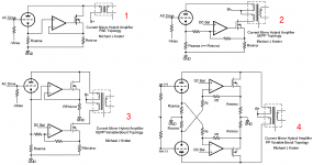
Here are some more design variations on the current (mirror) theme.
1. Boost an SE amp (need an OPT gapped for more DC than the tube alone, however, the Iq on the MOSFET only needs to be high enough to keep it in class A (see real-life load lines Power is scalable to a point.
2. Balanced SEPP gives exactly 2X power boost. This is the one I built and tested redrawn to show some parallel-ness.
3. SEPP with scalable power. like combining #1 and #2. This is the kenpeter circuit also.
4. Scalable push-pull. I suppose each side could be arranged to be connected like #1 also but this way might be more tolerant of tube variability if you get my drift... Other cleverness on DC balance...
5. There is a very simple way to use an enhancement mode FET like a 10M45/10M90 or the Supertex DN2540 to do #1.
cheers,
Michael
1. Boost an SE amp (need an OPT gapped for more DC than the tube alone, however, the Iq on the MOSFET only needs to be high enough to keep it in class A (see real-life load lines
Power is scalable to a point.2. Balanced SEPP gives exactly 2X power boost. This is the one I built and tested redrawn to show some parallel-ness.
3. SEPP with scalable power. like combining #1 and #2. This is the kenpeter circuit also.
4. Scalable push-pull. I suppose each side could be arranged to be connected like #1 also but this way might be more tolerant of tube variability if you get my drift... Other cleverness on DC balance...
5. There is a very simple way to use an enhancement mode FET like a 10M45/10M90 or the Supertex DN2540 to do #1.
cheers,
Michael
Attachments
There is a very simple way to use an enhancement mode FET like a 10M45/10M90 or the Supertex DN2540 to do #1.
The mosfets that you mention are depletion mode devices that require the gate to be more negative than the source.
I built an amplifier about 2 years ago using a 45 tube with one Fairchild FQP1N50 (G connected to D) in the cathode and 2 more as the other side of the current mirror. They were wired up like a typical mosfet current mirror (I work with a bunch of CMOS IC designers). The amplifier worked great until you pushed it into clipping, at which point one or both of the mirror fets shorted. After zapping a few mosfets I put the whole idea on hold.
I considered using the 10M45's as a current mirror but thought they would blow up because of the 450 volt rating. IXYS has shown the 10M90 on their web page for years, but no one had any in stock until recently. Mouser now stocks them and I already have 50 of them for some science experiments.
When I published the PowerDrive concept on my web page a few years ago, I got tons of very negative email condemning me for corrupting vacuum tube designs with "sand". One even suggested that I change my name to Transistorlab! After people actually tried using a mosfet follower to drive the grid of an output tube (very nice for A2 operation) they liked it and the idea is far more accepted than it used to be. Maybe it is time to sprinkle a bit more "sand" into the mix. Is it time for the "boosted triode SE"?
I put a hybrid amp schematic on my web site several years ago. It is sort of a darlington configuration with a 45 tube and a BJT. The few emails that I got were negative and the page received very few hits.
http://www.tubelab.com/SuperTubeSE.htm
The Un-transformer
The cathode resistor tap gets sized so as to provide approx. the correct drive signal to the Mosfet gate to support the same current ratio between tube and Mosfet as the N:1 turns ratio of the assymetrical balun requires for neutral flux.
Hence the name Un-transformer, since there is zero flux in the balun, while still transforming impedance 1/(N+1) by means of the ratio'd currents. (No voltage transformation though, so only N+1:1)
Can use two of them to do P-P of course. And can use two Un-xfmrs (with tubes and Mosfets) in totem pole configuration to get rid of the output xfmr altogether.
Don
Attachments
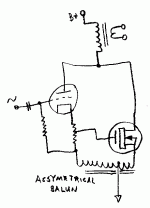
I should have explained that the assymetrical balun enforces the N:1 current ratio between Mosfet and tube by means of feedback to the Mosfet gate across the balun.
Picture the assymetrical balun as a teeter-tooter or lever like device. If the Mosfet pulls too hard, it tips voltage wise so as to turn the Mosfet off some. If the Mosfet doesn't pull hard enough, it tips so as to turn the Mosfet on more. The balun thus only has to handle the error voltages in the feedback loop. This means the balun can operate with far lower turns (or voltage rating) than the usual output transformer would have to.
Since the Mosfet maintains its output at N times the tube current, it effectively increases the tube Gm to (N+1)Gm. The output impedance of the composite assembly is also Rp/(N+1) since any changes in plate voltage on the triode have N+1 times as much effect on current flow (indirectly controlling the Mosfet too).
Don
A 6.3VAC or 12.6VAC filament transformer wired up in auto-transformer fashion should work for the assymetrical balun. Some frequency compensation (rolloff) on the Mosfet gate will likely be necessary to prevent oscillation. Can also use a ferrite balun xfmr, (or both types of xfmrs. in series on tube and Mosfet windings) to improve frequency response.
Oh, for DC stability/thermal stability, the Mosfet will need some small resistance in series with its source terminal. Maybe 1 Ohm (around 1/Gm of Mosfet) unless using a Lateral Mosfet where it is unnecessary.
This resistance will help match the Mosfet Gm versus the tube Gm tracking too. The tube cathode resistor then needs to provide for gate drive for the Mosfet and for the voltage drop across the source resistor at the N:1 ratio of currents.
Don
This resistance will help match the Mosfet Gm versus the tube Gm tracking too. The tube cathode resistor then needs to provide for gate drive for the Mosfet and for the voltage drop across the source resistor at the N:1 ratio of currents.
Don
tubelab.com said:
The mosfets that you mention are depletion mode devices that require the gate to be more negative than the source.
Oops, brain fart. I did mean depletion mode(normally on) MOSFETs
I built an amplifier about 2 years ago using a 45 tube with one Fairchild FQP1N50 (G connected to D) in the cathode and 2 more as the other side of the current mirror. They were wired up like a typical mosfet current mirror (I work with a bunch of CMOS IC designers). The amplifier worked great until you pushed it into clipping, at which point one or both of the mirror fets shorted. After zapping a few mosfets I put the whole idea on hold.
I considered using the 10M45's as a current mirror but thought they would blow up because of the 450 volt rating. IXYS has shown the 10M90 on their web page for years, but no one had any in stock until recently. Mouser now stocks them and I already have 50 of them for some science experiments.
Mouser stocks 10M90's until someone buys them out...
I wanted to order a few last week and they're currently OOS but I know where to get some now!
You probably went overvoltage at the low current end of the MOSFET swing when driving the tube into clipping. This is the normal mode of operation for SMPS (the snubber is not optional in SMPS circuits).
When I published the PowerDrive concept on my web page a few years ago, I got tons of very negative email condemning me for corrupting vacuum tube designs with "sand". One even suggested that I change my name to Transistorlab! After people actually tried using a mosfet follower to drive the grid of an output tube (very nice for A2 operation) they liked it and the idea is far more accepted than it used to be. Maybe it is time to sprinkle a bit more "sand" into the mix. Is it time for the "boosted triode SE"?
Funny thing about religious zealots; they show up everywhere.
I also build old school designs but also like to learn more by trying new things. I've learned a lot more about tube circuits by playing with this hybrid amp (ex. the load line analysis).
I think it's time to try a few more of these ideas. Interesting that you found BJTs sounded better. That will be worth a test in my topology.
Here's my idea on a depletion mode SE booster. The Iq on the MOSFET only needs to be enough to keep it in class A.
Michael
Attachments
You will want Rsense big enough in value to provide the approx. linear drive signal for the Mosfet in addition to the current feedback sensing to match the Mosfet current sensing Rmirror voltage. (since there is no Op Amp here)
This may push the gate voltage positive enough at tube idle current to allow an enhancement Mosfet (and so can delete Rbm and its cap. too)
[also, putting an assymetric balun in like I mentioned above will increase loop gain substantially too for closer current mirroring.]
Don
This may push the gate voltage positive enough at tube idle current to allow an enhancement Mosfet (and so can delete Rbm and its cap. too)
[also, putting an assymetric balun in like I mentioned above will increase loop gain substantially too for closer current mirroring.]
Don
"It looks like a classical Darlington."
Guess Mike could just put in a MJL4281A bipolar (350V, 230W 15A), in Darlington config., with rock constant Beta of about 150.
Could also go for the Sziklai pair too with a tube and MJL4302A. (PNP, constant Beta mate to the MJL4281A)
Don
Guess Mike could just put in a MJL4281A bipolar (350V, 230W 15A), in Darlington config., with rock constant Beta of about 150.
Could also go for the Sziklai pair too with a tube and MJL4302A. (PNP, constant Beta mate to the MJL4281A)
Don
If you want to see the hybrid concept taken to the extreme, look at my entry into this Microchip / Circuit Cellar design contest. They asked for designs using the new dsPIC chips from Microchip, so I entered a vacuum tube amplifier. It actually won one of the prizes. That design approached the concept of getting more power out of a vacuum tube amplifier from a different angle. I used a SMPS controlled by the dsPIC to adjust the voltage across the vacuum tube circuit in real time. The tube operates with a constant plate to cathode voltage that is very low (50 to 75 volts). This allows reduced dissipation in the tube, so the power output can be increased. Plate efficiencies of 70% and higher have been observed in SE amplifiers. 30 watts out of a single tube in SE mode is easy. You can download the entire project entry here:
http://www.circuitcellar.com/microchip2007/winners/MT2209.html
I now have amplifiers operating with the DSP based power supply replaced by a mosfet. The efficiency enhancement afforded by the SMPS is gone, since the mosfet is a lossy element, but the power output and distortion improvements are still present.
I think that the mainstream "religious zealots" that are common in the vacuum tube world would just choke on the dsPIC / SMPS design, but I plan on posting the mosfet based hybrid on my web site and possibly offering a PC board for it once it survives my usual torture testing.
tubelab.com said:I think that the mainstream "religious zealots" that are common in the vacuum tube world would just choke on the dsPIC / SMPS design, but I plan on posting the mosfet based hybrid on my web site and possibly offering a PC board for it once it survives my usual torture testing.
And some of us heathens might choke too - maybe lacking the requisite skill to carry it off (well me, anyway). A mosfet version seems manageable.
Sheldon
- Status
- This old topic is closed. If you want to reopen this topic, contact a moderator using the "Report Post" button.
- Home
- Amplifiers
- Tubes / Valves
- Another kind of hybrid