 I've converted 1/2 dozen of them so far.
Commercial 70 volt power amplifiers aren't really known for their low end so I wouldn't expect too much there. Actually it will run 6550's or KT88's the way it is. I have heard Bogans that people have just popped in some different output tubes and they sounded ok. I would loose the input transformer and the music/speech switch if it were me. If you wanted you could copy the Quicksilver which would allow you to use the easier found front end tubes.
The 8417 Quicksilvers will also work fine without changing the front end. A bias upgrade however I would highly recommend.
The 8417 Quicksilvers will also work fine without changing the front end. A bias upgrade however I would highly recommend.
What about the MO-100's? Look identical to the Quicksilver 8714 mono blocks to me or very close. I have access to a pair of these as well. I'm thinking of using the utility 9 pin socket for another stage of gain. These use 6550's of coarse, but look very similar to the Quickies.
shematic
shematic
Hi Burntfingers I hear you are the GOD of Quicksilver 8417 amps..Mine never sounded right once i did the KT 88 upgrade. Sign wave not symmetrical under load...Both amps have the exact same issues with theKT 88 's..Got the amps 7 years ago from my brotherinlaw , who was original owner...Reason for the change to KT88's, Two 8417 got damaged in shipping.Please help, Thanks Joe
I did not change the front end and the result was 45 volts peak to peak at 8 ohms...Are you getting full clean 60 volts peak to peak? I looked at a schematic from a Dynaco MKIII, they only use one tube 6AN8 to drive the KT88's..I'm wondering this is what I have to do get get the drive for the KT88 for full output,. Your thoughts ?
One of the links on that blog page you sent me Schematic, no longer exists
One of the links on that blog page you sent me Schematic, no longer exists
Quicksilver 8417 amps..
I just did a load of work on the Bogen which is almost identical.
KT88 are a totally different animal from 8417, but already the driver circuit is too weak in the original 8417 circuit to give good performance.
8417 are a very high gain high voltage modern valve (ie. low impedance) quite unlike anything else and a similar family to the modern 7591, which again neither resembles a 6V6 nor 6L6.
See it's quite similar
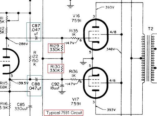
Substituting for the 7591
Drive requirements as a result are about 15-18V on the 8417, like the 7591 Versus about double or more on the KT or EL34.
If your circuit can't deliver linear drive and plenty of current (dictated by the line requirements of that type of phase splitter), then you will get lots of distortion in the driver, and mismatch in the OPT.
In this case I would say you will get more luck trying some high mu sweep tubes & reducing the HT rather than the mundane normal stuff.
I get way less power and the wavform at any audio frequency produces non symmetrical waveform, what gives?
What are you getting for output power into either a 4 ohm or 8 ohm load resistor in RMS volts?
The front end does have enough to run the amp to full power into a dummy load. I can produce 64 watts RMS into a 4 ohm load. I have symetrical waveform. You had one of the 23.7K resistors on your phase splitter that was measuring 100K. I had suggested that you change both of them. Did you? Is I mentioned in a PM look at the 12AX7 and see if the plate resistor and voltages are what I sent to you.
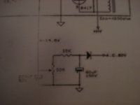
IN addition.... THe Quicksilvers the ones I have had in the past that weren't working correctly had problems in the cathode of the 12AX7 in that one or both of the resistors were out of whack. The resistor that is immediately on pin 8 should read 820 ohms and the resistor that goes from the 820 to ground should read 22 ohms not 220 as seen on the schematics that are floating on the internet. THe junction of the 820 and the 22 ohm resistors is where the feedback goes. NO, you canot remove the 820 ohm resistor. The voltage at the plate of the 12aX7 should be 145VDC.
If the voltage of 145 and the cathode voltage of pin 8 which should be .979 is correct and the resistor to ground is correct in value the amp should run fine.
When you have the correct voltages I suggest that you put in a new 12AX7 and see what the amp does now. My wave form is symetrical and also clips symetrical.
I have seen these amps produce 50-60 watts depending on the line voltage available and I will point out that my B+ is slightly higher because I have modified the power supply so that the 5AR4's act to ramp the B+ slowly while the diodes rectify the AC. ALso check your B+ voltage as the amp has age on it and the caps seem to go bad.
Last edited:
schematic
The feedback resistor is 562 ohms off the 8 ohm tap. The input resistor to ground on all the 8417's I've seen is 100K. The resistor to ground on the cathode leg is 22Ohms on all 8417's I've seen and 25 ohms on the original KT88 amps.
The feedback resistor is 562 ohms off the 8 ohm tap. The input resistor to ground on all the 8417's I've seen is 100K. The resistor to ground on the cathode leg is 22Ohms on all 8417's I've seen and 25 ohms on the original KT88 amps.
Attachments
Last edited:
I just did a load of work on the Bogen which is almost identical.
KT88 are a totally different animal from 8417, but already the driver circuit is too weak in the original 8417 circuit to give good performance.
8417 are a very high gain high voltage modern valve (ie. low impedance) quite unlike anything else and a similar family to the modern 7591, which again neither resembles a 6V6 nor 6L6.
See it's quite similar
Substituting for the 7591
Drive requirements as a result are about 15-18V on the 8417, like the 7591 Versus about double or more on the KT or EL34.
If your circuit can't deliver linear drive and plenty of current (dictated by the line requirements of that type of phase splitter), then you will get lots of distortion in the driver, and mismatch in the OPT.
In this case I would say you will get more luck trying some high mu sweep tubes & reducing the HT rather than the mundane normal stuff.
Or do what Dynaco did on there MKIII uses one 6AN8 tube to get the whole job acomplished
THANKS , I''ll get back you Friday eve..ThanksWhat are you getting for output power into either a 4 ohm or 8 ohm load resistor in RMS volts?
The front end does have enough to run the amp to full power into a dummy load. I can produce 64 watts RMS into a 4 ohm load. I have symetrical waveform. You had one of the 23.7K resistors on your phase splitter that was measuring 100K. I had suggested that you change both of them. Did you? Is I mentioned in a PM look at the 12AX7 and see if the plate resistor and voltages are what I sent to you.
IN addition.... THe Quicksilvers the ones I have had in the past that weren't working correctly had problems in the cathode of the 12AX7 in that one or both of the resistors were out of whack. The resistor that is immediately on pin 8 should read 820 ohms and the resistor that goes from the 820 to ground should read 22 ohms not 220 as seen on the schematics that are floating on the internet. THe junction of the 820 and the 22 ohm resistors is where the feedback goes. NO, you canot remove the 820 ohm resistor. The voltage at the plate of the 12aX7 should be 145VDC.
If the voltage of 145 and the cathode voltage of pin 8 which should be .979 is correct and the resistor to ground is correct in value the amp should run fine.
When you have the correct voltages I suggest that you put in a new 12AX7 and see what the amp does now. My wave form is symetrical and also clips symetrical.
I have seen these amps produce 50-60 watts depending on the line voltage available and I will point out that my B+ is slightly higher because I have modified the power supply so that the 5AR4's act to ramp the B+ slowly while the diodes rectify the AC. ALso check your B+ voltage as the amp has age on it and the caps seem to go bad.
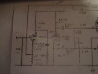
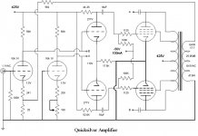
Quicksilver Schematic
In the schematic above I question how the second tube drives the driver tube as its grid is grounded and its cathode is not tied to the first tube's cathode, hence it is not amplifying or inverting an input signal or tracking the signal of another tube. is there something I'm missing?
In the schematic above I question how the second tube drives the driver tube as its grid is grounded and its cathode is not tied to the first tube's cathode, hence it is not amplifying or inverting an input signal or tracking the signal of another tube. is there something I'm missing?
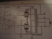
I know i am re-opening an old thread but i have just changed the driver circuit of a pair of old Quicksilver 8417s according to the KT88 schematic posted by Burnedfingers in #15.
I have 2 questions:
1. are the input tubes still 12AX7 / 12BH7 or is 6922 used somewhere?
2. question from Ejam in #17: "in the schematic above I question how the second tube drives the driver tube as its grid is grounded and its cathode is not tied to the first tube's cathode, hence it is not amplifying or inverting an input signal or tracking the signal of another tube" - in practice it works as the driver triode cathodes are coupled by the common cathode resistor, but i also wonder if the second half of the input tube is only used for bias setting of the second tube. Is there something missing in the schematic?
I haven't read the whole thread, but I am very familiar with the Bogen design and the QS appears to be a copy of it. The Bogen is brutally simple. Half a 12AX7 as VA into half a 12AU7 as concertina. Both combined in a single 7247 bottle.
To convert to any other power tubes, it's simple enough to re-bias the final tubes. But you still have 2 other issues:
1. The gm of 8417 is at least double of any other tube you use. So you will have a drive issue. You either lose a lot of power or you redesign the driver. Reducing the GNFB could help with gain but you have to see if the concertina can swing enough for your tubes.
2. You have to look at the 8417 load line and that of your proposed tube substitute to see if the existing OPT impedance will work.
The circuit proposed in #15 attempts to solve some of these issues by changing to a Mullard topology. I don't know how well it works but yes, the second tube does nothing.
- Home
- Amplifiers
- Tubes / Valves
- Quicksilver conversion