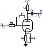
mashaffer said:Sorry, brain fart. This one is the basic circuit. How is it biased with the grid floating like that?
It's not. Someone was drawing an "anode follower" and simply forgot to add the grid DC return.
There is another possibility, but they were sloppy in the schemo: the grid DC return could possibly be via a second stage grid resistor, since this is a capacitor coupled design. It it's just one stage (as in a line stage) the output end would require a paralleling resistor to provide a DC return.
Yes, it is supposed to be a CC stage with local feedback but it seemed to me that we needed a grid resistor from the junction of Rf and Rg to ground. However, since I don't really understand grid leak bias I thought that there might be something there that I was missing.
mike
mike
mashaffer said:Yes, it is supposed to be a CC stage with local feedback but it seemed to me that we needed a grid resistor from the junction of Rf and Rg to ground. However, since I don't really understand grid leak bias I thought that there might be something there that I was missing.
mike
Mike you are right. There needs to be another resistor, either where you stated, or in the following stage. The stage would then be operating in self-bias, where the voltage necessary to bias the valve is developed across the cathode resistor. The grid resistor serves to hold the grid at essentially ground potential. This is not grid leak bias.
For grid leak bias, if the grid of the triode is connected to common through a large resistor, say 5M or 10M ohms, a negative voltage will build up on the grid. This is caused by electrons colliding with the grid wires and giving the grid a negative charge. Grid wires are pretty small, but they are large enough that electrons do accidentally run into them. The large resistor allows this charge to leak off slowly and electrons are constantly striking the grid so a steady DC voltage builds up there. This voltage is enough to bias the valve without any resistor in the cathode. This type of biasing was common in the first stage of microphone inputs on PA amplifiers and in the first audio stage of table radios. Of course, the chief advantage to this setup is economy; a working amplifier stage with very few parts. The chief disadvantage is relative poor bias voltage control and no practical way to measure it.
Hope this helps your understanding a little.
Wade
I'm using this circuit in a microphone preamp and I put the DC reference on the "input end" of Rg to keep it out of the Rg/Rf circuit (I use Rg/Rf as a gain control element to avoid the issues with global loop feedback.)
As mentioned, DC return could be through the following stage Rg or interstage, or input transformer, etc. but it's just not shown in the schematic fragment.
As mentioned, DC return could be through the following stage Rg or interstage, or input transformer, etc. but it's just not shown in the schematic fragment.
- Status
- This old topic is closed. If you want to reopen this topic, contact a moderator using the "Report Post" button.
- Home
- Amplifiers
- Tubes / Valves
- Ground reference