Not ideal situation....
But if you do try it, Tie G1 to the cathode or it will self destruct by excess current/volts through G1!
connecting G1 to cathode will make it electrically 'invisible' to the valve....
Has the 6336 got separate cathodes per section...?--Not familiar with it....
As to current, volts drop etc, who knows!
BTW, where in Wales are you...?
I'm in Swansea....
You can make a mediocre rectifier that way, yes. It will take 30 watts of heater power, timer circuitry to prevent application of power until the heaters are completely warm, and will give you a max output current of 300mA or so per section. The drop will be higher than a GZ34; at 100mA, the drop will be about double. The max voltage will be considerably lower.
Seems a waste of a perfectly good regulator tube. A cheap GZ34 will do a much better job.
Seems a waste of a perfectly good regulator tube. A cheap GZ34 will do a much better job.
Or you can try these:
http://cgi.ebay.com/SVETLANA-5C8S-1...ryZ58174QQssPageNameZWDVWQQrdZ1QQcmdZViewItem
The sockets are a bit hard to find, but they're easy enough to make.
John
http://cgi.ebay.com/SVETLANA-5C8S-1...ryZ58174QQssPageNameZWDVWQQrdZ1QQcmdZViewItem
The sockets are a bit hard to find, but they're easy enough to make.
John
poynton said:I have a few 6336s.
Could I use one as a rectifier by strapping the grids to the anodes and commoning the cathodes ?
If so, what would limit the current? The grid ?
The load ! As with any rectifier

Wasn't WE who used a 845 as a rectifier for another 845 ?
Yves.

pls dont try 6336 as rectifier,,,,6336 is a nice tube for output stage ..SE ..PP ,,or parafeed
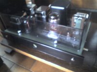
I second that. The 6336A works great in SE output stages. Just think of it as three 6AS7's in parallel. I have one running in a cathode follower output stage that sounds great. Power is about 10 WPC with distortion at 0.5%.
Attachments
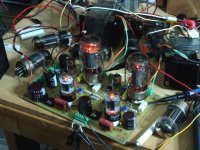
Just curious: could you post or pm the schematic of your 6336A -SE? Could not find it on your site.
The amplifier was one of my augmented cathode follower experiments. The entire thread can be found here:
http://www.diyaudio.com/forums/show...d=114021&highlight=augmented+cathode+follower
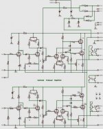
The amp works very good, but I still view it as an experiment, one of many, with many more to come. I have included the Eagle schematic file, but some component values are missing. The input and driver tube is a 6EM7. The dual triode feedback tube is a 12AX7 and the output tube can be a 6AS7, 5998, 7236 or 6336A. I would not advise anyone to copy it directly expecting it to work without some tweaking. I am now experimenting with a version using mosfet for the top output tube section. I also did a digitally controlled cathode follower for a microcontroller design contest. A vacuum tube amplifier actually won a prize in a sea of microprocessor controlled gizmos. The details, including schematics and source code can be found here (click entry to download the entire contest submission):
http://www.circuitcellar.com/microchip2007/winners/MT2209.html
Attachments
- Status
- This old topic is closed. If you want to reopen this topic, contact a moderator using the "Report Post" button.
- Home
- Amplifiers
- Tubes / Valves
- 6336 as a Rectifier