hi i have one of these little amps it is the EL34 version i must say the sound is very good i paid £160 for it. the guy who had it before me had changed the valves but he said he never ajusted the bias. i am hopeing that it is a fixed bais, as i have not a clue were to start with byassing has an y one got one of these amps
all help would make me very greatful
all help would make me very greatful
Actually I think you want self biased in this case as "fixed" bias is more likely to need adjusting. I tried to find a schematic for you but google came up dry. I suspect it is probably PC board based making it hard to trace the circuit but why not try to locate the cathode resistors on the output tubes and report back the color code on them?
Be careful of leathal voltages and stay way from those power supply capacitors!
mike
Be careful of leathal voltages and stay way from those power supply capacitors!
mike
Simple question, are there any pots other than a volume control (if fitted) that are accessible either directly or through small holes in the chassis? If you see no means for adjustment it is most likely that the amplifier is cathode biased and no adjustments are required. (Or possible without mods.)
If you are unfamiliar with tube/valve amplifiers, and it sounds like you are -- you should read the safety and newbies thread here before taking the bottom cover off of this amplifier.
If you are unfamiliar with tube/valve amplifiers, and it sounds like you are -- you should read the safety and newbies thread here before taking the bottom cover off of this amplifier.
Two of the pots are for hum-balancing the heater supply (one for each channel). The other two pots adjust potential dividers used in the paraphase inverters, to get proper balance (one per channel again). The cathode resistors are big grey ones in mine, though I can't remember the value off hand.
I've been running a Mengyue Mini for about a year and spent the last couple of days drawing up a schem and checking it out. It's a sweet & nice amp just the way it is, but the urge to modify is strong...here is the schem of mine: (as it came, unmodified)
http://i198.photobucket.com/albums/aa160/birdy81260/6P1Mengyue.gif
As you can see mine is the 6P1 model with 6N2 phase splitter tubes. Build quality is a bit shabby. My amp is specified for 220V and that is what I run it at in Australia with an APC Line-R 600 (www.apc.com). I find I have 6.3V on the heaters on one channel and 5.6V on the other channel. If I run it at 230V I get 7.0V and 6.3V. I should be able to sort that out with a low value resistor in the higher voltage heater cct. I also found a DC voltage on the control grid of one of the output tubes, around 4V to 6V. Could not isolate it, seems to be coming from the control grid itself, swapping capacitors and 6N2's and 6P1's did not isolate the "problem". Grid voltage rises and cathode voltage falls, not what I expected. Amp still sounds good so maybe not a problem, but a question I need to find an answer too. Just learning here...
I would like to find a thread somewhere for people with cheap Chinese amps in general, so we could share schems and mods or rebuilds with another circuit entirely etc. I have 3 different Chinese amps to help my learning curve") I find PCB's a pain to modify and rework, so a point to point with tag strips is not far away, in fact, quite close But as I said at the start it sounds good as it is.
I find PCB's a pain to modify and rework, so a point to point with tag strips is not far away, in fact, quite close But as I said at the start it sounds good as it is.
http://i198.photobucket.com/albums/aa160/birdy81260/6P1Mengyue.gif
As you can see mine is the 6P1 model with 6N2 phase splitter tubes. Build quality is a bit shabby. My amp is specified for 220V and that is what I run it at in Australia with an APC Line-R 600 (www.apc.com). I find I have 6.3V on the heaters on one channel and 5.6V on the other channel. If I run it at 230V I get 7.0V and 6.3V. I should be able to sort that out with a low value resistor in the higher voltage heater cct. I also found a DC voltage on the control grid of one of the output tubes, around 4V to 6V. Could not isolate it, seems to be coming from the control grid itself, swapping capacitors and 6N2's and 6P1's did not isolate the "problem". Grid voltage rises and cathode voltage falls, not what I expected. Amp still sounds good so maybe not a problem, but a question I need to find an answer too. Just learning here...
I would like to find a thread somewhere for people with cheap Chinese amps in general, so we could share schems and mods or rebuilds with another circuit entirely etc. I have 3 different Chinese amps to help my learning curve
I find PCB's a pain to modify and rework, so a point to point with tag strips is not far away, in fact, quite close But as I said at the start it sounds good as it is.I live in the UK, and my mains voltage is 245V, but the design is the same as yours, so my HT was up over 300V. It was remarkably powerful, but the output valves and PT were on the verge of melting! I completely rebuilt mine (made a turret board) for less (safer!) power, and better performance.Ian444 said:I also found a DC voltage on the control grid of one of the output tubes, around 4V to 6V. Could not isolate it, seems to be coming from the control grid itself, swapping capacitors and 6N2's and 6P1's did not isolate the "problem". Grid voltage rises and cathode voltage falls, not what I expected. Amp still sounds good so maybe not a problem, but a question I need to find an answer too. Just learning here...
One problem I encountered was that one of the heater supplies was connected (or shorted?) to ground on one side, inside the transformer, which obviously caused problems with my hum-balance pot. I had to remove the pot and just leave it with one heater leg grounded, without any problems. I wonder if your odd heater voltages, or grid voltage, could be due to something similar?
Sorry to keep raving on, I hope it is useful to someone.
"I find PCB's a pain to modify and rework"
that is - when you have to pull out 6 valves and a selector switch and volume pot, and have the PCB with wires coming from it trying to lift it up enough to get components out from underneath, etc. Point to point has advantages.
Just been listening to the amp the last couple of hours and it seems to have found bass that was missing before. I adjusted the pots on the phase splitters for each channel to give the same amplitude at the output of the OPT for each channel for the same given input. I was expecting that pot to adjust the positive vs negative going amplitude of the sine wave coming from the OPT...yep I'm a newbie...need to thunk about it. This is the best it has ever sounded, a bit of rework is all I have done....me and the missus are havin kittens listening to Ed Kuepper.....
Don't like it when I don't know what I've done to make it come good, but same thing with another Chinese amp I have, maybe the first thing to do is rework the whole PCB, but some of them aren't really that easy to work on, as in access to the PCB is difficult.
Update, I bought a $30 TA2020 Tripath amp on a PCB and $20 SMPS to power it, it blows my valve amps into the weeds, I have already spent approx $2500 learning about valves, and this $50 setup is better, by far, especially so after the input caps were bypassed (edit - that is, no input caps, deleted). I doubt that with another $2500 and everything I have learnt that I could build a better valve amp to match the TA2020. I am very happy to find a good sound. I have never heard a commercial SS amp sound anywhere near this good either. I won't be building any more valve gear or tranny gear for a while All recordings are played back truthfully. Just my opinion. I'm shattered but happy. There you go, thems the breaks....that's audio!
All recordings are played back truthfully. Just my opinion. I'm shattered but happy. There you go, thems the breaks....that's audio!mengui el 84
Hallo everybody---I do possess such Mengui el 84 amp---I have had it tweaked-changed the tiny blue caps and the electrolytes----now It has huge AUDYN caps an alps pot too------I am sure I could do better----the sound is rather thin and the bass is booming---anyway I am using it in a 3 way electronic x over ed 3 stereo amps---situation---the main highs tube amp is in the works for tweaking too----this Mengui after 35 minutes or so of operation , if listened in stand by----there is a noise like cracking paper!!!!! what s the reason?????
anybody can help???? cheap --no value chinese tubes??? or what???? thanks
Paulo
Hello, i need some help.
does anybody knows how to setup the potential dividers used in the paraphase inverters?
Two of the pots are for hum-balancing the heater supply (one for each channel). The other two pots adjust potential dividers used in the paraphase inverters, to get proper balance (one per channel again). The cathode resistors are big grey ones in mine, though I can't remember the value off hand.
Reply With Quote
does anybody knows how to setup the potential dividers used in the paraphase inverters?
Update, I bought a $30 TA2020 Tripath amp on a PCB and $20 SMPS to power it, it blows my valve amps into the weeds, I have already spent approx $2500 learning about valves, and this $50 setup is better, by far, especially so after the input caps were bypassed (edit - that is, no input caps, deleted). I doubt that with another $2500 and everything I have learnt that I could build a better valve amp to match the TA2020. I am very happy to find a good sound. I have never heard a commercial SS amp sound anywhere near this good either. I won't be building any more valve gear or tranny gear for a while
Slightly O/T.....
Yup, The TA2020 Tripath amp is pretty good sounding. I played around with them near 8 years ago--They were the latest thing then--Still got a Dev. kit with the TA2020 on around here somewhere...
One thing to remember. The Input Caps are there for a reason. Any DC levels on the Inputs will appear on the Outputs of the low-pass filter and on the speaker....
--DC imbalances like this will cause excess dissipation in the switching-MOSFETs on the chip and can make the device get hot, and could cause speaker damage, due to dc current flow.....
--Best replace 'em with Good Quality 4.7uF caps--The originals are not known to be great quality parts.....
--Never ever run more than 14 V supply to the chip, the MOSFETS in there are rated for an absolute Max of 16V. I found out the hard way!
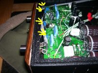
I had one of these forgotten in the closet and I took it out over the weekend, repaired and modified it. Some safety definetely aspects need attention, stability was dreadful, and some critical parts are too cheap and needed replacing. So here goes:

1. Mains power is routed to the front panel power through a signal-type coaxial cable. This violates western world safety standards. In addition, the power switch is mounted in the most unfortunate location electrically-wise, that is the power cable runs alongside the input signal cables. I got rid of the very cheap two-input selector and I moved the power switch to its location, bottom side of the picture. This way the mains cable is far away from all small signal circuitry and cannot induce hum.
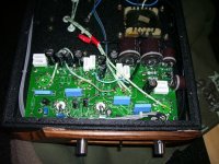
2. Next was the cheapest volume pot. Out with that and in with a 100K Alps one.
3. The input signal connector affair is cheap and I replaced it with a pair of some no name-ish teflon parts.
4. Small-signal cabling was unscreened ribbon cable, and it needs to go. I changed the length from the RCA jacks to the pot with VDH D-102 MKIII. The portions from the pot to the tubes, and from the output to the feedback resistors were also replaced with same type cable, shields removed and wire pairs twisted to reduce impedance.
5. The board was extremely dirty with sloppy hand soldering flux remains, which I had carefully cleaned with isopropyl alcohol.
6. The dreadfully magnetic carbon 100K resistors strapped across the input tube grids were removed altogether, as they are in parallel with the pot and modify its logarithmic characteristic. The Alps pot will not loose contact and upset the tube bias.
7. 2K RN55 grid stoppers were added to the inputs, as the amp would oscillate wildly when the pot was turned down.
8. My amp had some 2.2meg resistors strapped from the output tube anodes to their grids. This is something I have never seen in any textbook or even in an on-line schematic. It of course had the effect of reducing open-loop gain, whilst hurting phase margin. Out with them.
9. Two of the four anode load 75K resistors had gone open, so I replaced all four with 75K RN65s.
10. One of the four 220uF caps that bypasses the o/p tube cathode resistors had dried out, so I replaced all four with Panasonic FC 560uF/35V that I had lying around.
11. The EL84s did not have grid stoppers, a clear no-no. Added 4x 1K1 RN55s by lifting pin 2 from the board.
12. Checking stability with a 5KHz squarewave on the scope showed that some, but not much compensation was in order. Paralleled the feedback resistors with 220pF silver mica caps. The optimum value was determined on the bench.
1. Mains power is routed to the front panel power through a signal-type coaxial cable. This violates western world safety standards. In addition, the power switch is mounted in the most unfortunate location electrically-wise, that is the power cable runs alongside the input signal cables. I got rid of the very cheap two-input selector and I moved the power switch to its location, bottom side of the picture. This way the mains cable is far away from all small signal circuitry and cannot induce hum.
2. Next was the cheapest volume pot. Out with that and in with a 100K Alps one.
3. The input signal connector affair is cheap and I replaced it with a pair of some no name-ish teflon parts.
4. Small-signal cabling was unscreened ribbon cable, and it needs to go. I changed the length from the RCA jacks to the pot with VDH D-102 MKIII. The portions from the pot to the tubes, and from the output to the feedback resistors were also replaced with same type cable, shields removed and wire pairs twisted to reduce impedance.
5. The board was extremely dirty with sloppy hand soldering flux remains, which I had carefully cleaned with isopropyl alcohol.
6. The dreadfully magnetic carbon 100K resistors strapped across the input tube grids were removed altogether, as they are in parallel with the pot and modify its logarithmic characteristic. The Alps pot will not loose contact and upset the tube bias.
7. 2K RN55 grid stoppers were added to the inputs, as the amp would oscillate wildly when the pot was turned down.
8. My amp had some 2.2meg resistors strapped from the output tube anodes to their grids. This is something I have never seen in any textbook or even in an on-line schematic. It of course had the effect of reducing open-loop gain, whilst hurting phase margin. Out with them.
9. Two of the four anode load 75K resistors had gone open, so I replaced all four with 75K RN65s.
10. One of the four 220uF caps that bypasses the o/p tube cathode resistors had dried out, so I replaced all four with Panasonic FC 560uF/35V that I had lying around.
11. The EL84s did not have grid stoppers, a clear no-no. Added 4x 1K1 RN55s by lifting pin 2 from the board.
12. Checking stability with a 5KHz squarewave on the scope showed that some, but not much compensation was in order. Paralleled the feedback resistors with 220pF silver mica caps. The optimum value was determined on the bench.
Attachments
Last edited:
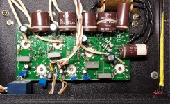
Next was adjusting the symmetry 50K pots with a scope for equal amplitude signal on the output tube grids, and the 500R hum-balance pots. I then performed some measurements.
Comparing open and closed-loop gain shows us that there is some 5.2dB worth of feedback. Reasonable.
Inserting and removing a 8.2R load on the output allows us to calculate the output impedance, found to be about four ohms, with feedback of course. So damping factor is ~2. This makes for a current mode amplifier, rather than a voltage one. So, well-behaved speakers are in order. I hooked up my Proac Studio 120s.
- Home
- Amplifiers
- Tubes / Valves
- Mengyue mini valve amplifier