This schematic is from " An approach to auio frequency audio desgin"
Its a 30 watt KT-88, what do you think about it? Is it worth building?
I have a large transformer to use, outputs of 400-0-400 no load, and outputs for filaments. No real idea of current, but the core is pretty big 3 1/4"X4 1/4"X 3 1/2".
Other amps you have built, that sound goos, but are still rather simple?
Thanks
Jeremy
Its a 30 watt KT-88, what do you think about it? Is it worth building?
An externally hosted image should be here but it was not working when we last tested it.
I have a large transformer to use, outputs of 400-0-400 no load, and outputs for filaments. No real idea of current, but the core is pretty big 3 1/4"X4 1/4"X 3 1/2".
Other amps you have built, that sound goos, but are still rather simple?
Thanks
Jeremy
JoshK said:Why is that, Eli? I don't see what in particular about this design would make that so (I am still learning).
Josh,
Multiple caps. in the signal path, along with GOBS of loop NFB, make the design EASY to destabilize. The very last thing you want in an amp is to satisfy Barkhausen's criterion for oscillation. A 180 degree phase shift, unfortunately, does exactly that.

Notice that there are 2 signal path caps. in each leg of the amp. Right away, that's 120 degrees. Mediocre "iron" can EASILY provide the remaining 60 degrees.
Please examine the Mullard circuit. That topology has but 1 signal path cap. in each leg of the amp. So, it's MUCH more difficult to destabilize that topology. Cap. induced phase shift is only 60 degrees.
Eli Duttman said:Jeremy,
That's Williamson topology. Only creme de la creme O/P "iron" works in that style of circuitry. Otherwise, the phase shifts will make your life miserable.
That's unfair criticism of a circuit topology that's stood the test of time. I regulary design 4 stage amps with nom 20dB global feedback and can get til 36dB before instability sets in.
I disagree with you on the Mullard 20Watt amp. One of the reasons it's stable is the very low pole of the phase splitter mentioned in Morgan Jones amp book page 415-417. I've listened to the 20Watt amp and it sounds very flat.
I regulary use concertina phase splitter and there is absolutely nothing wrong with it. If the previous section is DC coupled to the concertina, then really it becomes a 3 stage amp in disguise. So many amps have 2 sets of interstage coupling caps and although you mention the theoretical phase shift disadvange, in practise the problems are eclipsed. Work the problem...
I regulary place orders for 150W o/p transformers based on Williamson design practises, although 18 sectioned and pricy, I consider them cremé-de-la-cremé .
richj
Rich,
There is absolutely nothing wrong with the Williamson topology. As you said, it HAS stood the test of time. Built with GOOD "iron", it gets the job done. I merely remind folks that Williamson used VERY special Partridge made trafos in his original. Don't build a Williamson amp with Hammond O/P trafos.
While I like Mullard's topology, I don't like their tube selection. Circuits that employ loop NFB should use high gm types in the small signal positions, to provide resistance against slew limiting. The 6SN7 Williamson used is reasonably high gm.
Eli, what puzzles me is that earlier designs were never really sussed out for IM thd, and I found the driver stages were often blamed for poor performance. (preceeding stage is a concertina)
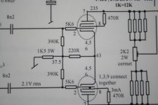
Enclosed is a modified driver circuit I regulary use,
typical of Williamson but seems never to have been followed up in other push-pull voltage driver designs. (RCA did it in a 50W juke box amp). The cathode/ g1 feedback on each side is a glaring obvious, and the common cathode greatly assists in stage balance and to top it, a pot is used in the anode loads to balance out thd. I find it a darned good stage and with 12BY7's as triodes, the b/w performance and output impedance (appro 1.5K) is exemplorary in parallel o/p stage p-p amps.
Strangely enough Morgan Jones doesn't even touch this.
The inclusion of a 10 Ohm resistor in each cathode leg of fixed bias o/p stage tubes is well known.
As with the above comments, I'm sure is a major contributer in the excellent sonic performance of my amps. This is tipping on a massive technical subject, but -> Has anyone done a computer simulation ?
richj
Attachments
Eli, you've made this statement in several threads and I've been dying to ask what you mean.Circuits that employ loop NFB should use high gm types in the small signal positions, to provide resistance against slew limiting.
ray_moth said:
Eli, you've made this statement in several threads and I've been dying to ask what you mean.
Ray,
It has to do with the HF error correction signal. In order to avoid "smearing" or (WORSE) a complete block, the small signal circuitry has to be able to swing lots of Volts, quickly. High gm types provide the requisite capability.
Among the many causes of bad sound, slew limiting and O/P trafo core saturation are (IMO) particularly annoying.
This agrees with my findings that high gm tubes as drivers have the very stuff to make good sounding amps with fast transient response..Amps like Citation from Harman K are renown for excellent sound quality., other tubes like EF184 also group offer good performance.
Anyone come across the lonely12HG7 or 12GN7A ?
Back to the first post, alot of amplifiers with such circuits were built for simplicity, the output stage g2 to anode snubber components must be fitted. Good quality output transformers are still made by Sowter and others..
richj
Anyone come across the lonely12HG7 or 12GN7A ?
Back to the first post, alot of amplifiers with such circuits were built for simplicity, the output stage g2 to anode snubber components must be fitted. Good quality output transformers are still made by Sowter and others..
richj
Funny you should mention these. I bought a heap of them when I built my 813T PP class A beast several years ago, and have been looking at Pete Millett's data again today whilst napkin sketching some ideas for a reasonably powerful midbass amp, say 50-300Hz.richwalters said:Anyone come across the lonely12HG7 or 12GN7A ?
I like Patrick Turner's JBS2323 design based around the 6CM5, which I have about a hundred of.
http://www.turneraudio.com.au/2323-triode-integrated-6cm5.html
Idea was 6 6CM5 in PPP with a net 3k3 a-a load from a Lundahl LL1620. Drivers using the 12HG7 or GN7 trioded in a LTP to drive the outputs. NFB taken to the other grid in the LTP, and probably a 7N7 to give enough gain. 54W triode watts, mostly in class A. Should be OK methinks.
Another thought about 12GN7's .The input capacitance is highish (i.e g1 close to cathode) which is making be think twice about how the previous stage might behave... data sheet also mentions not putting g1 with too high volts.
My own opin, this (and all) RF tubes is better fed from a Lo Z source.
Although I've tried these tubes in lieu of 12BY7's, I did notice on upper audio f tests that THD does increase, probably due to to input capacitance of 12GN7 tubes slightly misbalancing the HF performance of the concertina p/s. The siblings 12BY7 and or EF184 may represent the best performance compromise ever to be obtained.
richj
Any one know where i can find the schematic mentioned in this thread? I have a couple dozen 807, i'd like to take a look at it, I tried the linky, but the page has moved. I'd like to try 807, because i have them on hand, i don't have any KT-88, and they are getting kind of pricy for me,
THanks for all the replies
Jeremy
THanks for all the replies
Jeremy
Richj,
Your modified driver circuit in post #9 seems reminiscent in spirit to some other approaches I've seen, which I think are oriented toward reducing the odd harmonic signature of differential stages.
a) Using a "twin tail" on the cathodes: usually two degen. resistors from the cathodes to the tail resistor or CCS with additional high value resistors tacked onto the cathodes to ground.
b) In RC-30, page 696, I see two odd high value resistors R12,R14 from cathode to grid, beside the usual biasing resistors?
I think, (but untested) these schemes heuristically take advantage of the usual increase of the cathode tail voltage at the voltage swing extremes of the diffl. amp when the tube turning off is going too slowly. The positive feedback connections from the moving tail to the turning on tube (which has higher gm by then) helps speed it up or increases the tail current range above the CCS level so as to maintain linearity better.
From the simple triode fromula: gm = K Ip^.3333
Obviously, a constant current tail alone is not sufficient to maintain a constant gm1+gm2, necessary for linearity, when they are non-linear functions of current.
Beside this problem, there is also the Island effect (Inselbildung) from grid wire proximity to the cathode, which causes prolonged lower gm near cutoff (probably looking like a dropping K factor or .3333 exponent in the formula above)
This is an area that is sorely in need of some modeling in Spice or actual circuit testing with a spectrum analyzer. The diffl stage, probably the most commonly used circuit around, and not a bit of distortion compensation analysis in the literature that I am aware of. (probably is in some obscure paper out there somewhere, anyone with info? Well, I have seen the WE harmonic equalizer literature, but not anything on these other compensation approaches)
Don
Don,
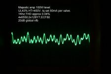
I've enclosed clip of thd at 100W, note regular harmonics with a touch of hum. This isn't a one-off performance and I get the same result using ECL82's pents strapped at triodes with different ressy values, but the gain is so measly low requiring the preceeding phasesplitter to shovel more volts. (+12dB) each side from concertina.
The only reference I've seen with localised cath to g1 feedback is in Radiotron 4th ed p.332 which describes in effect a bootstrap, i.e the input Z is raised. In the p-p voltage common cath driver circuit I use, the result effectively eases the AC loading on the concertina (HF balance is improved) then the driving stage grid resistors could be raised in value, but again I've detected sonic differences when lower value interstage caps are used. This may be a tempting approach but the end result causes increased thd at the HF end caused by circuit strays and interactions with rising impedances.
Hence the cue for best performance in p-p amps is to carefully provide a symmetrical layout from in to out.
The concertina p/s already provides the lowest thd,
so the optimum driver circuit with the one I use is the only way in getting 50+50V RMS drive, with considerable overhead. (stage gain of each 12BY7 is 27dB which is approaching double compared to ECL82) in sim config.) for the same thd ! Not bad-
There is another crude description in the GEC book (design of an audio ampf) page 9, but only generalises and mentions the pot in the anode circuit becomes far more responsive as a result of the high cathode resistance. This is obvious.
comments welcome
richj
Attachments
I agree largely with previous posts, only we must be careful when counting contributing phase shifting elements.
The cathode bypassed resistors also contribute, although shifting back later and can thus be used remedially. In that sense the Williamson topology has 4 phase-contributing elements. The Mullard ltp topology actually also has 4 - one tends to neglect the grid grounding cap of the phase inverter (although again its contribution is different, it is still there). Then there is the added G2 bypass [again shifting back later (lower down)], which can make matters worse. (And all the time one disregards the power decoupling caps - hopefully they are big enough!)
Counting in this fashion, I am using a Williamson topology with all of 5 capacitive low frequency shifting elements - 3 coupling caps, a G2 bypass and a cathode bypass. But it is stable with up to 30dB of NFB (I use only 20dB). Point is that what Eli said is true, but with the relative small physical size of caps these days, it is quite feasable to get l.f. stability with several stages. Naturally, a mediocre output transformer will compound the problem, but that can be avoided.
That point made, I am also fond of the "Mullard" topology, using the G2 bypass to steer clear of oscillation-prone areas in the phase diagram.
Sorry, Diesel_Tech,
Your original question about the fig. 4-4 design seems to have gone unanswered. Yes, I would trust a GEC design, but note the output transformer specs. Then, this design is from 1957, when as said above capacitors were physically big.
These days you could happily change C4, C5, C10 to 50 or 100uF depending what you can get. I would also greatly increase C8, C9 to 1000uF/63V types, or even 2200uF/63V. (I hate this splitting of power tube cathode resistors only for the sake of some equalisation, adding a further time constant - I would rather put an Ia balancing pot somewhere. But as they are there, get the phase shift out of the way as far as possible.) For the same reason I would also increase C1 to some 470uF/16V (I have poor experience of lower voltage electrolytic caps).
We then come to the main remaining phase elements: C2-R8 and C6-R14 (and equivalents in the other phase). The choice would tie in with the output transformer choice. My own feeling is for a greater difference in these time constants, but .......
- Status
- This old topic is closed. If you want to reopen this topic, contact a moderator using the "Report Post" button.
- Home
- Amplifiers
- Tubes / Valves
- KT-88 from a book