Hi,
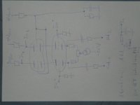
I found a major problem in my design: The feedback loop is wrong.
I have to take the signal for this from the upper valve's cathodes and put it to the gates of the differential amp.
Dick: Is this correct? The disadvantage I see, that i decrease input resistance with this solution. How did you manage this???
Regs, Dirk
First of all I use a coupling capacitor between upper tube cathode and the ESL stator.How did you manage this???
After this coupling capacitor (no DC!) I take the signal to the cathode of the first stage via a string of resistors ( string must be capable of handling 5kV).
This feedback is done for each side of the diff. amp.
Dick
Hi Dick,
wouldn't this be a problem, because the input stage would run on about 12mA each branch, while the output tubes are at about the same? I never thought about this before, because "sand amps" had around 1000 times more current in the output stage... So shouldn't we better put the feedback therefore on the gates???
(The Acoustat HV stage couples back to the transistor's base...)
Dirk
I'm sorry, no time to make schematics - two days of housebuilding...!!! ;-((((. Will care for this soon!!!
Dirk,
Sorry for the late reply, my spare time is very limited.
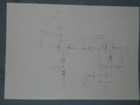
The output stage is OK, should work fine with the values I gave you.
If you use PL519, you can use a floating 40V~ filament transformer for the upper tube, and at the same time make 50Vdc out of it for the screen supply.
For the Cascode, ground the – input at the signal input ground for max CMRR.
The DC blocking capacitors at the feedback are not needed, are already present at the output. Use protection diodes to protect the CCS for excessive voltage peaks.
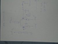
Without a lowpass filter at the input the amplifier will sound very bright. Try 50k series resister, hereafter a series connection of 3nF and 50k pot to ground. Yes, I know it’s very low pass, but thrust me you will need it. Play with the 3nF value if the tone is not satisfying.
I’m not shure about your auto bias, better is to insert a 10 ohm resistor inbetween bottoms tube cathode and ground to measure bias current.
Once adjusted and stable it won’t drift much when properly made.
Dick
Sorry for the late reply, my spare time is very limited.
The output stage is OK, should work fine with the values I gave you.
If you use PL519, you can use a floating 40V~ filament transformer for the upper tube, and at the same time make 50Vdc out of it for the screen supply.
For the Cascode, ground the – input at the signal input ground for max CMRR.
The DC blocking capacitors at the feedback are not needed, are already present at the output. Use protection diodes to protect the CCS for excessive voltage peaks.
Without a lowpass filter at the input the amplifier will sound very bright. Try 50k series resister, hereafter a series connection of 3nF and 50k pot to ground. Yes, I know it’s very low pass, but thrust me you will need it. Play with the 3nF value if the tone is not satisfying.
I’m not shure about your auto bias, better is to insert a 10 ohm resistor inbetween bottoms tube cathode and ground to measure bias current.
Once adjusted and stable it won’t drift much when properly made.
Dick
- Status
- This old topic is closed. If you want to reopen this topic, contact a moderator using the "Report Post" button.
- Home
- Amplifiers
- Tubes / Valves
- DD amp for ESLs...