300B Cathode Bypass Capacitor Value / Options?
What size capacitor I use for a 2A3 or 300B cathode bypass?
Simple question, Right?
Here is what I’ve seen:
1. 100uf seems to be the most popular
2. Seen values as low as 20-30uf for a 2A3
3. Some use 3 capacitors, one each on pin 1 and 4, and 1 on the hum pot. I’ve seen 3-50uf and 3-10uf… Sometimes with the caps on pin 1 and 4 bypassed with lower values.
4. Then some people bypass the main capacitor with 2 lower values:
100uf, then 1uf, then .001uf
5. And then there’s the Ultapath, which adds a capacitor from the B+ to the + side of the cathode bypass cap.
(This is what I used in my current amp)
So the choices are all over the map, 20-100uf with 1 to 5 capacitors… What do you folks prefer?
sgerus said:300B Cathode Bypass Capacitor Value / Options?
So the choices are all over the map, 20-100uf with 1 to 5 capacitors… What do you folks prefer?
Fixed bias. That way, I don't have to worry about it.

dsavitsk said:I agree wth fixed bias in theory, though my 300b amps are ultrapath (50uF). But, to determine the standard bypass cap, use
(Rp + rp) || Rk
and plug this into
C = 1/(2 * pi * F * R)
where the above is R, and F is your 3dB roll off frequency.
Shouldn't that be:
Rk || rk where:
rk= (Rp + rp) / (1 + u)
D'oh! My first day of law school, one of my professors was referring to some law and pulled out a copy of the statute to look at it to make sure he had it correct, even though he had written it in the first place. The lesson, of course, was not to assume you remember something but to look it up to be sure you are correct.
Miles, Could you explain why you don’t have to worry about it with fixed bias?
Let’s look at the formula.
Given:
RL=3000 (OPT)
Ra=700 (JJ300B)
U=3.85 (JJ300B)
Cathode bypass Res=1K
Rk=(3000+700)/(3.85+1)=762R
r’k=1K//762R=432R
At 20K hz 1/(6.28*20*432)=18uf
At 10K hz 1/(6.28*10*432)=37uf
At 5K hz 1/(6.28*5*432)=74uf
At 4K hz 1/(6.28*4*432)=92uf
At 1K hz 1/(6.28*1*432)=368uf
Based on this, 18uf is good for 20hz, which is also the rating of most OPT’s
Using 100uf is good for <4hz, which seems like overkill?
My current amp is set up with a 100uF oil for the cathode bypass and a 20uf for the ultrapath….. Think I’ll do some testing over the weekend!
sgerus said:Miles, Could you explain why you don’t have to worry about it with fixed bias?
Let’s look at the formula.
Given:
RL=3000 (OPT)
Ra=700 (JJ300B)
U=3.85 (JJ300B)
Cathode bypass Res=1K
Rk=(3000+700)/(3.85+1)=762R
r’k=1K//762R=432R
At 20K hz 1/(6.28*20*432)=18uf
At 10K hz 1/(6.28*10*432)=37uf
At 5K hz 1/(6.28*5*432)=74uf
At 4K hz 1/(6.28*4*432)=92uf
At 1K hz 1/(6.28*1*432)=368uf
Based on this, 18uf is good for 20hz, which is also the rating of most OPT’s
Using 100uf is good for <4hz, which seems like overkill?
My current amp is set up with a 100uF oil for the cathode bypass and a 20uf for the ultrapath….. Think I’ll do some testing over the weekend!
Because with fixed bias the cathode (or filament in the case of a dht) is grounded, there is no cathode resistor and hence no need to bypass it with a cap. Negative bias voltage is applied to the grid.
Incidentally when I go for cathode bias I usually use 100uF with a 20uF cap for hum cancelling alla Western Electric, but like Miles I much prefer fixed bias for this application.
By the way 100uF is not overkill, it really depends a lot on the primary inductance of the transformer, the L, R, C present in the output circuit conspire to create a series resonant circuit which at the secondary actually appears to look like a low to moderate Q parallel resonant circuit which at resonance can produce a significant boost in low frequency response - depending on where the boost occurs it can result in flabby, overblown bass, or worse can pump a significant amount of subsonic energy into your speakers if present at the input of the amplifier. (record warps, etc.)
The above is just another reason why I prefer fixed bias. (Transparency, ease of tweaking op point for "voicing" the amplifier, etc.)
By the way you meant Hz not kHz right?
Here’s a follow up on some listening tests with different value cathode bypass caps for the 2A3:
I tested 3 values, from one extreme to another:
1. 200uf Mallory electrolytic bypassed with a with a 2.2uf Solen
2. 100uf Oil
3. 18uf E-Speaker Audio Cap
My test was rather crude…. Turn off the amp, jumper in the new cap, turn the amp back on and listen, then repeat with other caps.
My preference for right now after only 2 hours of listening is that the high quality 18uf cap sounds best. Of all the pentode driven (WE91 type) amp schematics I found, 16uf was the lowest value shown, with the average being 63uf.
In interesting side note: An “unofficial” schematic of the Wavelength Cardinal shows a 39uf Solen used for the 300B bypass.
Now I need to wire in a switch for the bypass cap’s and so some “Blind” listening tests.
I wonder if my crude test proved that to some point, quality is more important than a higher value uf?
Yes cap quality is critical here which is why I use fixed bias whenever feasible, and you may also be getting some "pleasant sounding" low bass boost with the 18uF that would be subsonic with larger values of bypass cap. Can you measure the frequency response of your amplifier to see?
Can you measure the frequency response of your amplifier to see?
Sorry, I don't own or know how to use a scope.
If any DYI menbers live in the Milwaukee area and have the time or desire to help me with this, please let me know!
all of that Fo formulas are simple not true...
I tryed the lot of Ck "formulas"
and when I am try to apply the sound was not good at all...
when i try to simulate with pspice I came the conclusion
for 2A3, and could be taken like almost every output tube
that Ck value is in strongly connection with Inductance of primary
of OT, and C at the Vb a little...
for 2A3 when Lp=22H, Ck is about 20uF for the best low end response
I cant remember now for the 300B but the story is the same
anyway
the bigger Lp and the lower Ck
for clear and fast bass...
for the simple R load of input tubes, You could go for the higher values
but every tube is different...
also could be of use to start with lowwer values 22-47uF
first use the upper formula to determine
the right walue of signal C, input R and calculate for the -3db at 1,6Hz
that will be -0.25db at 20Hz app.
cheers
Here are the test results of the frequency response of my WE91 Clone with different cathode bypass caps (for the 2A3-40)
Thanks to diyaudio member Ziqzaqflex for making house calls with an oscilloscope!
See this thread for info on the amp in general:
http://www.diyaudio.com/forums/showthread.php?s=&threadid=109140
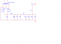
I have attached an updated schematic for reference
With a 18uf Clarity Cap for the bypass and a 3.9uf Solen for the Ultra path
31.5Hz – 15KHz @ -1dB
Adding 100uf Oil Cap in parallel to the 18uf
22Hz – 15KHz @ -1dB
Adding 200uf Mallory in parallel to the 18uf
23Hz – 15KHz @ -1dB
Back to 18uf on the cathode and a green LED for the pentode (in place of a cheap 100uf)
30Hz – 15.8KHz
We did notice sever clipping on the bottom of the sign wave at around 15KHz
Power output was 6.125 Watts before severe clipping with .544V input…
This is in line with the load line plot of the 2A3-40
Thanks to diyaudio member Ziqzaqflex for making house calls with an oscilloscope!
See this thread for info on the amp in general:
http://www.diyaudio.com/forums/showthread.php?s=&threadid=109140
I have attached an updated schematic for reference
With a 18uf Clarity Cap for the bypass and a 3.9uf Solen for the Ultra path
31.5Hz – 15KHz @ -1dB
Adding 100uf Oil Cap in parallel to the 18uf
22Hz – 15KHz @ -1dB
Adding 200uf Mallory in parallel to the 18uf
23Hz – 15KHz @ -1dB
Back to 18uf on the cathode and a green LED for the pentode (in place of a cheap 100uf)
30Hz – 15.8KHz
We did notice sever clipping on the bottom of the sign wave at around 15KHz
Power output was 6.125 Watts before severe clipping with .544V input…
This is in line with the load line plot of the 2A3-40
sgerus said:We did notice severe clipping on the bottom of the sign wave at around 15KHz
Scott: I don't recall this clipping at 15K per se. The only time we had clipping was when we drove the amp hard at the 500mV level, to the 6W output. The clipping was essentially independent of frequency. I mention this only because your statement might be misinterpreted to imply you have some odd clipping behavior based on frequency.
Far as I can tell, the amp works fine, though I was a little surprised that HF response dropped as early as it did. Maybe this is normal, IDK. What we didn't do, in retrospect, is check the FR of the pentode input isolated from the 2A3 grid. I would be interested to learn where the rolloff occurs. Could just be an anemic driver ??
Quality install, Scott. Nice workmanship.
Hi Zigzagflux,
I would suspect the high source impedance of 60K from the pentode based driver stage in conjunction with the miller capacitance of the 2A3 probably completely accounts for the rolloff. According to a quick calculation the -3dB point is around 45kHz, and it would be ~0.8dB down at 15kHz if the transformer was absolutely perfect.. (Assuming Cstrays + Cmiller of 60pF for the 2A3.)
I would suspect the high source impedance of 60K from the pentode based driver stage in conjunction with the miller capacitance of the 2A3 probably completely accounts for the rolloff. According to a quick calculation the -3dB point is around 45kHz, and it would be ~0.8dB down at 15kHz if the transformer was absolutely perfect.. (Assuming Cstrays + Cmiller of 60pF for the 2A3.)

FYI, the rectumfriers are TV dampers, the lower value .22 filter input causes more L input filter action hence lower Vout but better reg, the choke is a Hammond (I beleive it was 81-82 ohm spec'ed), The 220uF is a 550V Jenson and the 10uF an RXF Mundorf, also a 50W Mills bleeder, the 82uFs are Solen PP, I draw about 87mA. Amazingly similar PS
- Status
- This old topic is closed. If you want to reopen this topic, contact a moderator using the "Report Post" button.
- Home
- Amplifiers
- Tubes / Valves
- What size capacitor I use for a 2A3 or 300B cathode bypass?